AVI AVI
AVI
AVI
A COVID-19 contribution developed in self isolation:
Handicraft fire proof ECANDLES for chandeliers in heritage houses
The following is a detailed instruction of how to build ECANDLES for chandeliers as a measure to protect against fires. With the exception of the light bulbs, all materials used to build the ECANDLES are reutilized consumer waste products. The ECANDLE are carefully optimized to make them reliable and easy to handicraft. This work was also done in order to prepare a possible project for the “Tueftellabor Einstein” in Zug, Switzerland. Due to the COVID-19 problematic, we had to close our laboratory during the lock-down. Most of us as coaches are pensioned seniors and a bi- to tri- weakly close contact with youngsters is at the moment out of question. Social distancing is not an option when introducing youngsters into handicraft.
We thus present a step by step instruction of a project which is of general interest and can easily be done at home using all present home tools such as scissors, pliers, and drill bits. All materials used are available, even during the lock-down: miniature light bulbs for ovens, aluminum packing materials, including beer cans and effervescent compressed capsules packing. Indeed, helping to strengthen my immune system as a preventive measure against COVID-19, I decided to do a multi vitamin cure taking a capsule of Supradyn energy once a day. I have already started to build ECANDLES, using the shorter tubes of Pretuval, an anti flue drug, before the outbreak of COVID-19. When I tested the longer tubes of Supradyn, I discovered that the greater length of these tubes, greatly improved the performance and reliability of the ECANDLES.
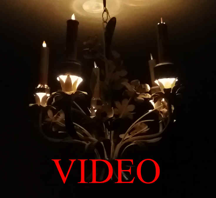
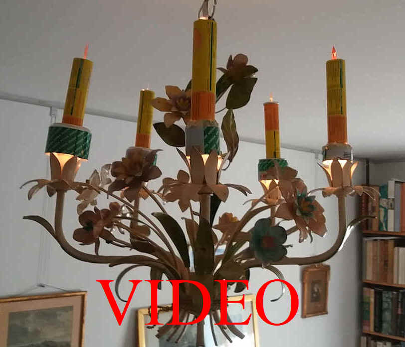
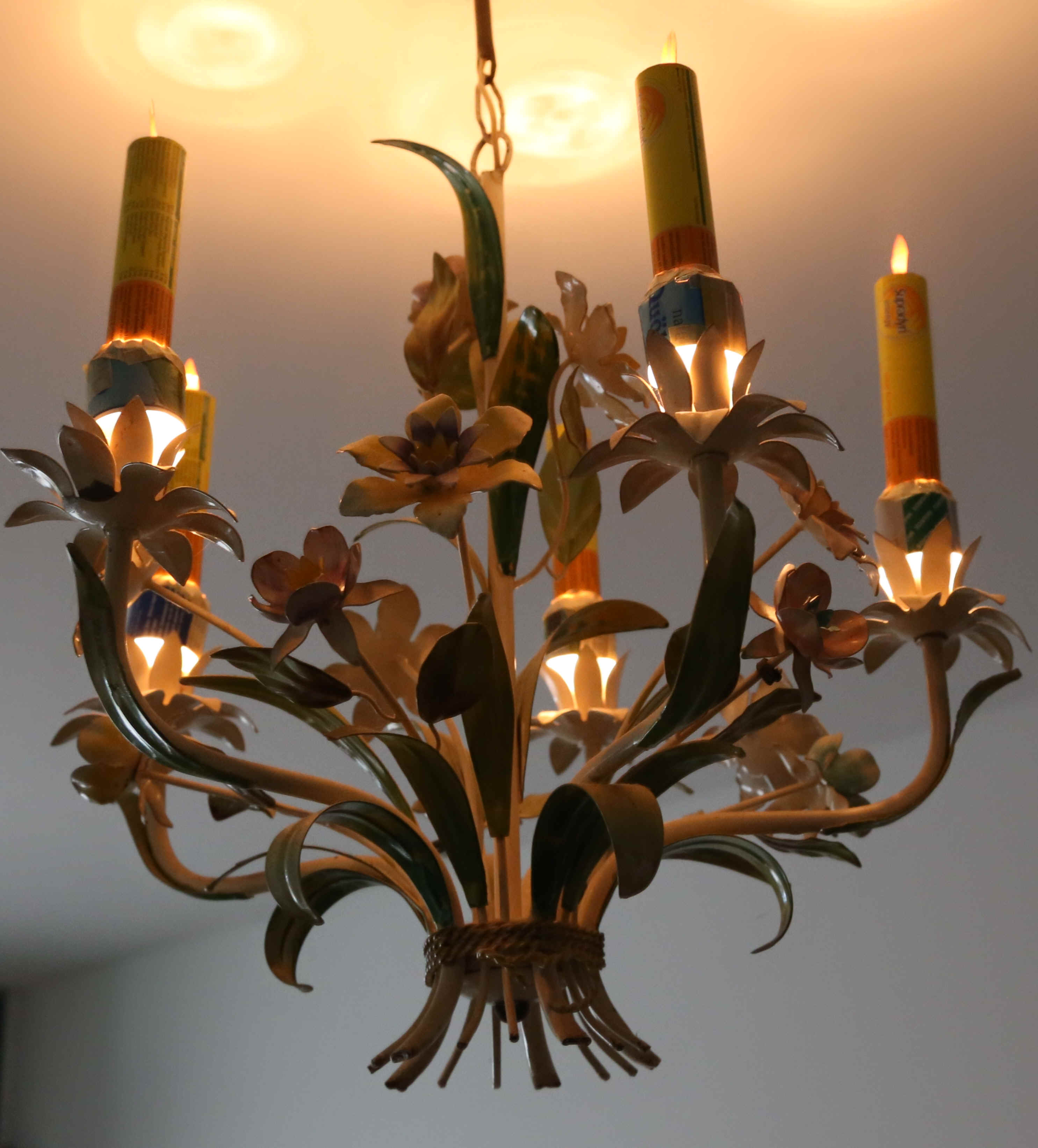
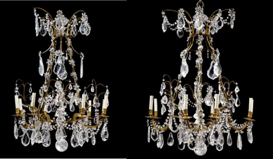
After having bought two superb 1720 rock crystal chandeliers for my heritage protected property, Chateau d'Epanvilliers - Museum of old Games, in France, which is open for tourists during the summer month July and August, I searched for ECANDLES. This has to do with the new trend in France, to offer night visits with candle lights. For me it was out of question to use normal candles for fire hazard reasons. Chandeliers always use the narrow gage electric screw light bulbs. I quickly realized that no such ECANDLES are on the market, so I had to come up with my own solution. An effort was made to re-utilize materials as much as possible in the design!
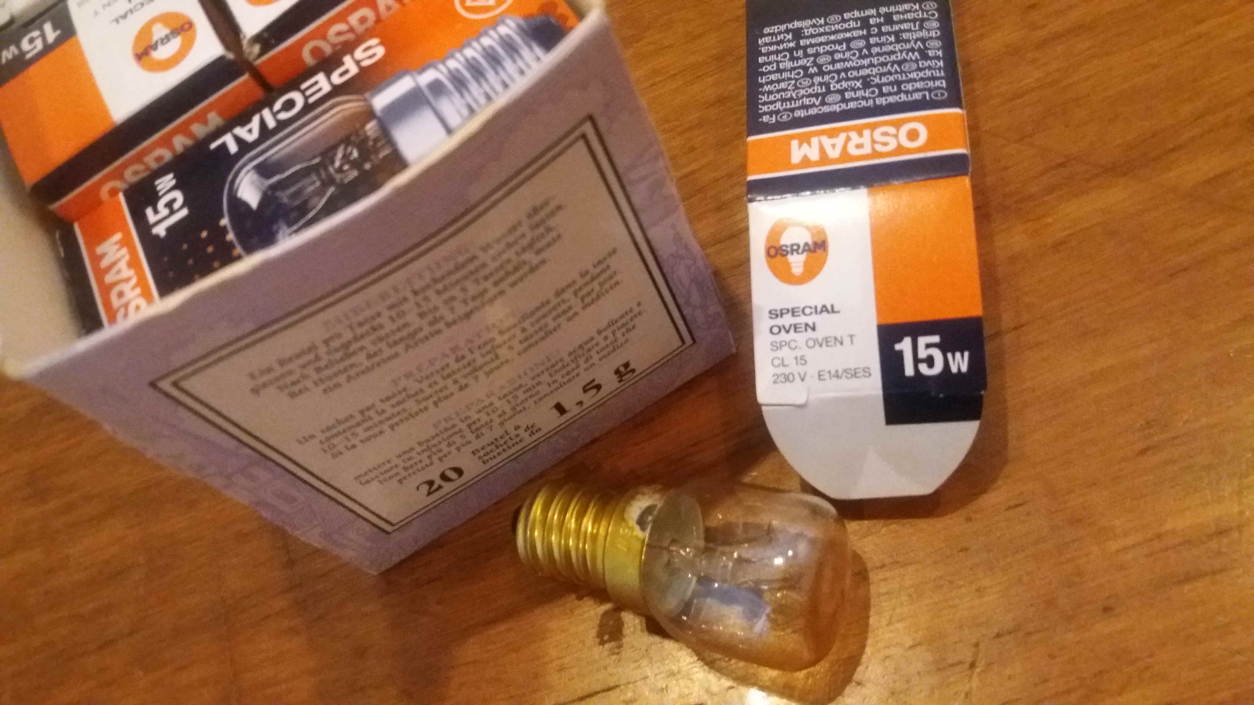
Considering LED solutions, one is confronted with the problematic combination of having limited space, the volume of a candle, and the fact that chandeliers are wired up for 220 Volt, but Led's use low voltages. I stumbled on the solution by discovering the miniature light bulbs which are sold for the lightning of household backing ovens. Indeed, these light bulbs not only support high temperatures, they also produce a lot of heat! The heat produced by the SPECIAL OVEN 15w -85lm OSRAM light bulbs (SPC OVEN T CL15 230V - E14/SES, www.ledevance.com) can be used to do some useful work and permit to build hot air driven turbines.
Step by step procedure for building ECANDLES in 9 steps: 1) Materials, tools
and templates used; 2) preparing the tubes by cutting the bottom and 3) drilling
4 air holes; 4) making, centering and sharpening the turbine holding spring; 5)
cutting and forming the rotor; 6) gluing the flame on a jeans rivet on top of
the rotor and fitting the rotor to the tube; 7) making a spring holder for the
ECANDLE; 8) building a light shade around the four air holes; 9) final assembly,
testing and painting the ECANDLES.
1) Materials, tools and templates used.
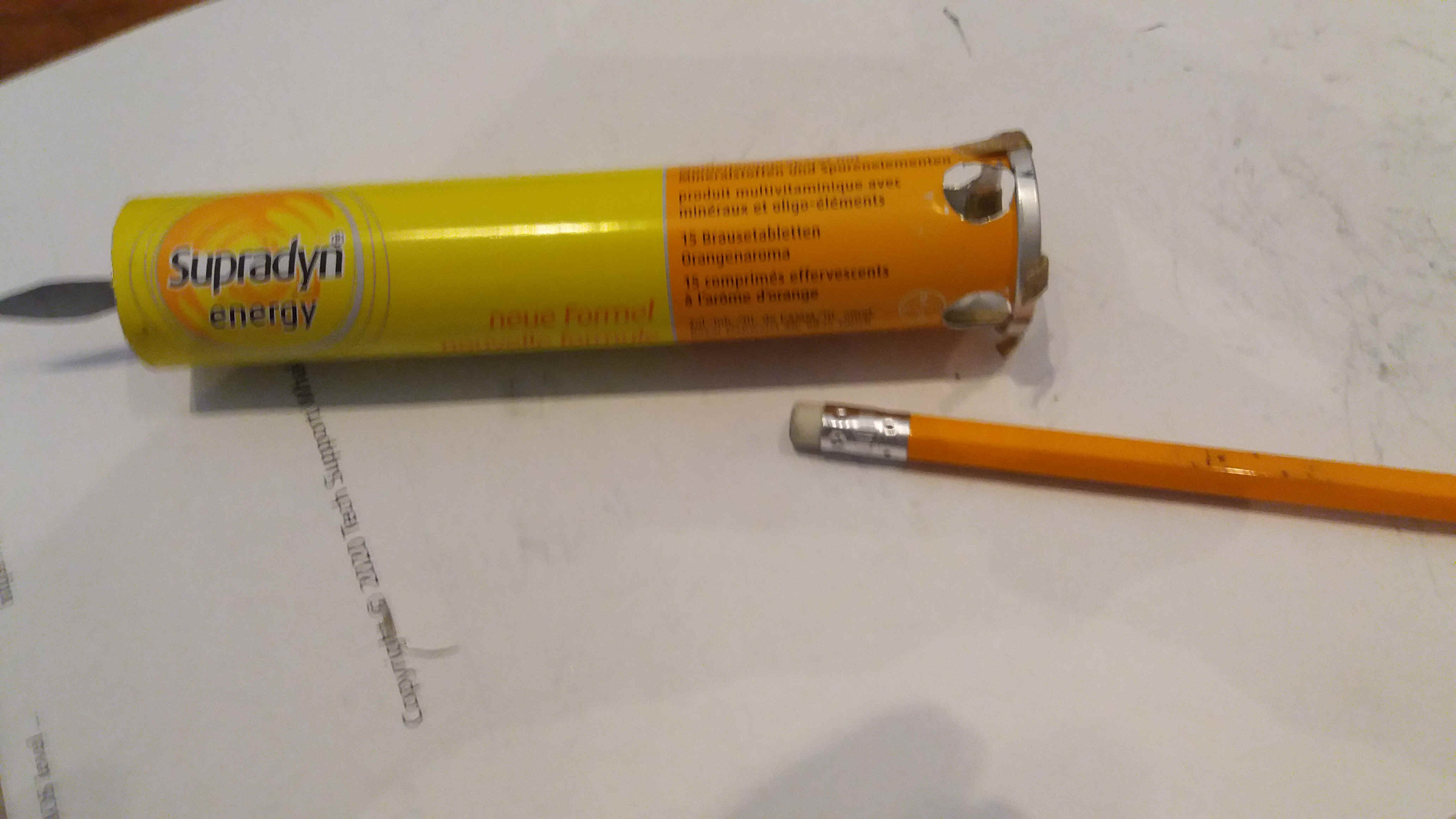
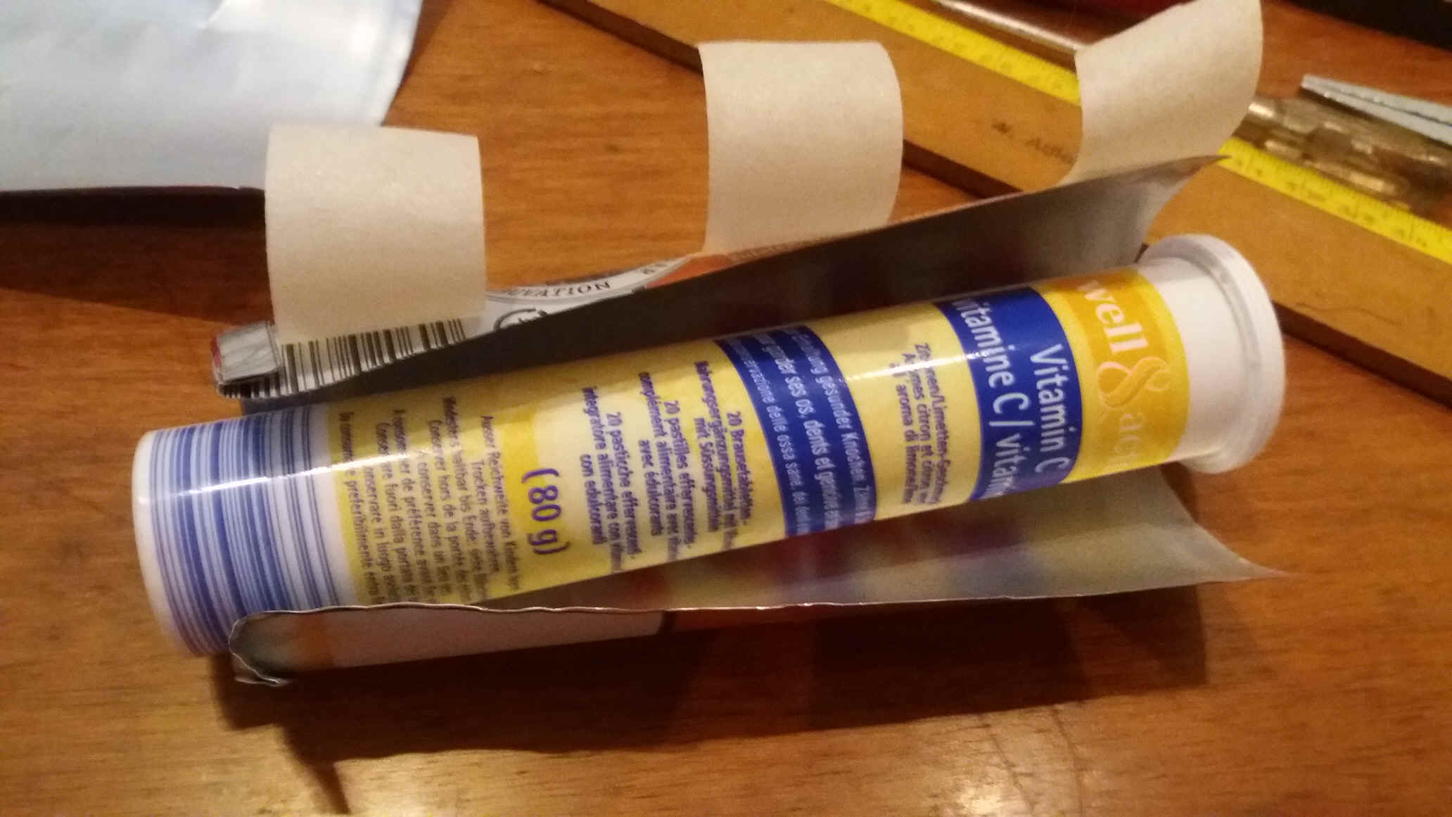
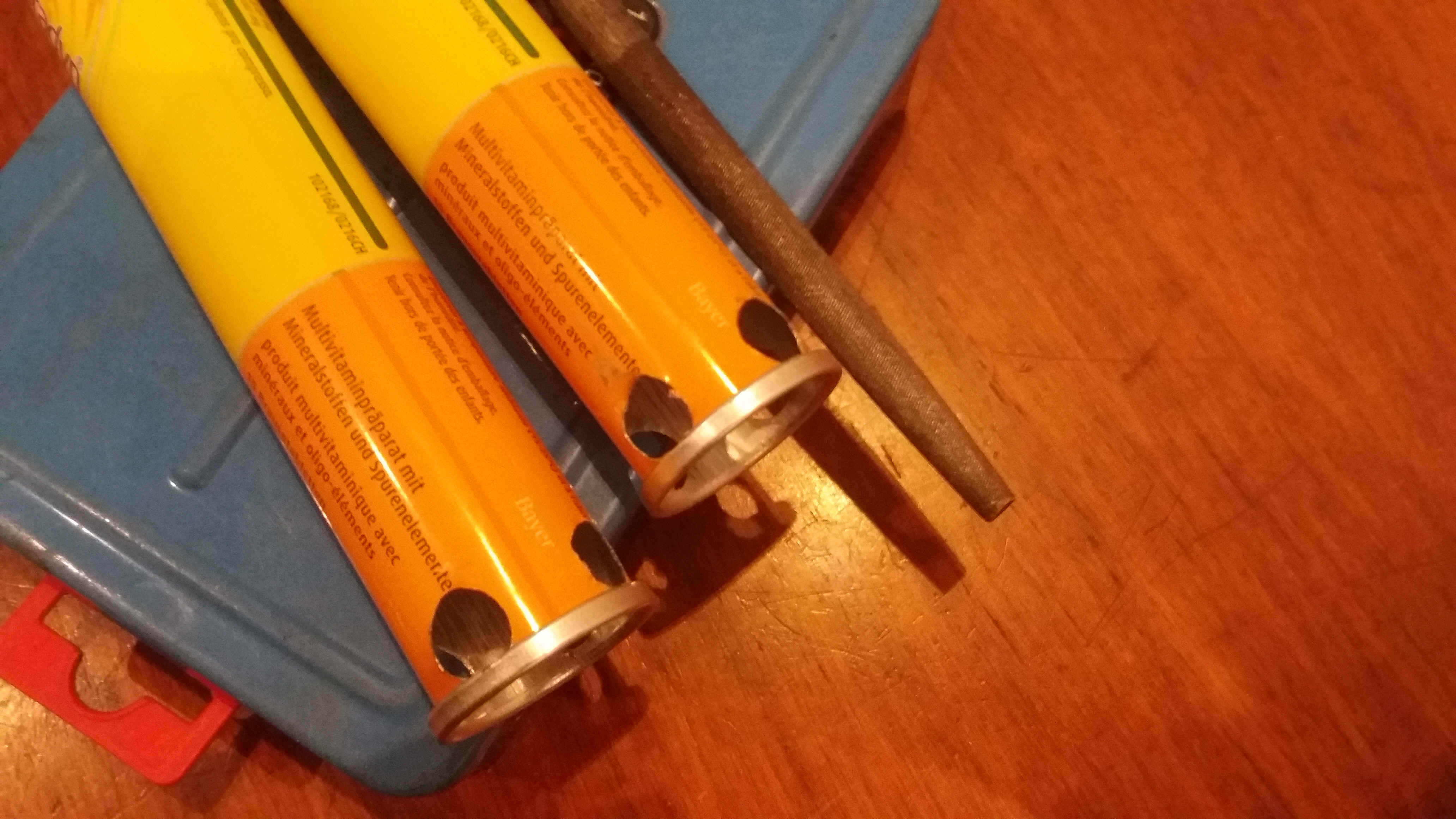
The light bulb is shown in the preceding picture and an already prepared
Supradyn effervescent compressed capsules tube is shown below. Note the eraser
topped pencil, which will be used to place the rotor holding spring inside the
tube. To the right one sees the air holes which we have to drill into the tubes.
All of the remaining aluminum parts, rotor, flame and light shade, are made from
cut aluminum soft drink or beer cans. For the rotor bearing spring and the
bottom holding spring we use a 1mm gage lightly spring acting stainless steel
wire. Stainless steel or hard copper rivets are used for the bearings – see 6).
Masking tape is used for making the light shades of 8).
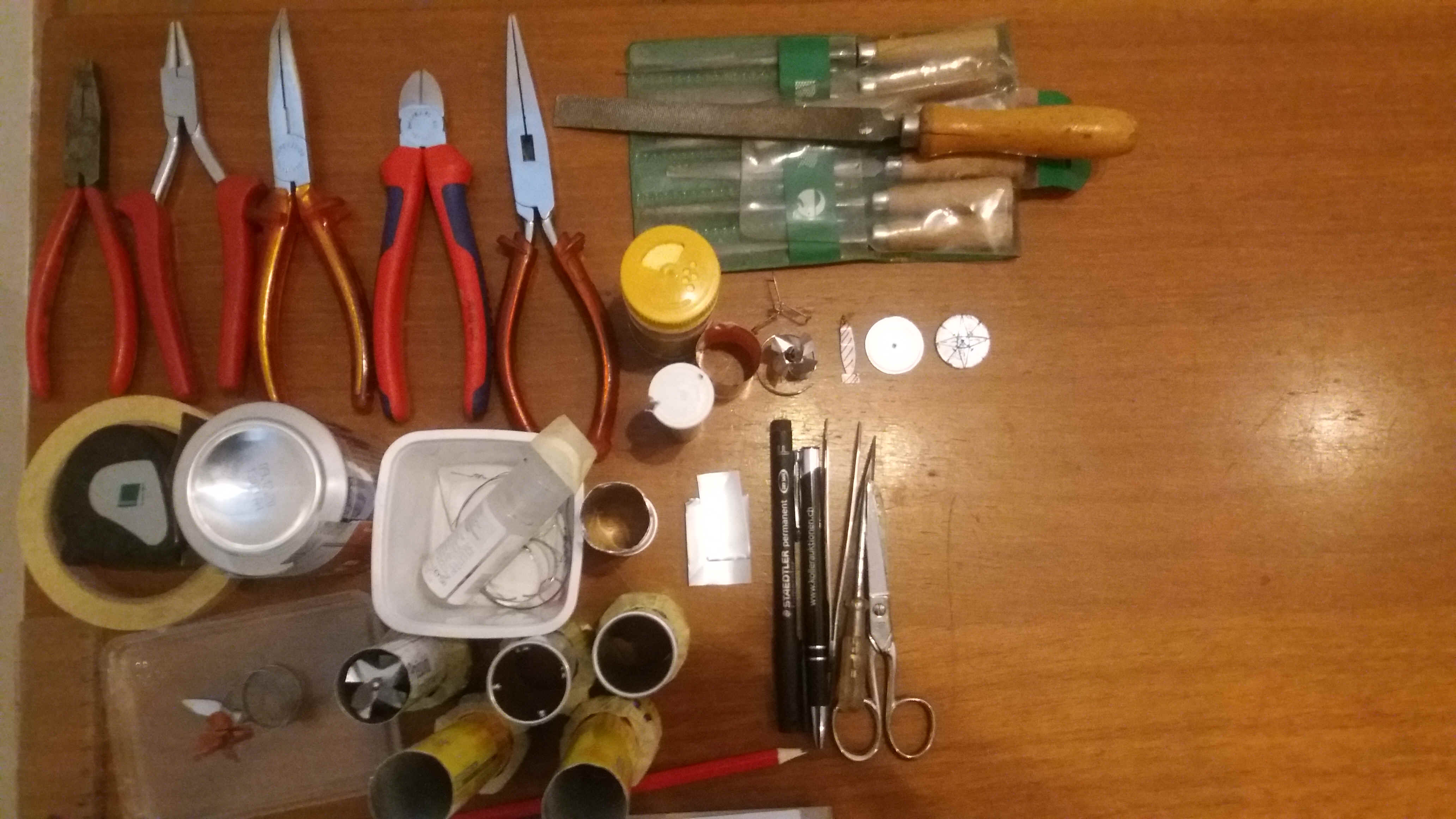
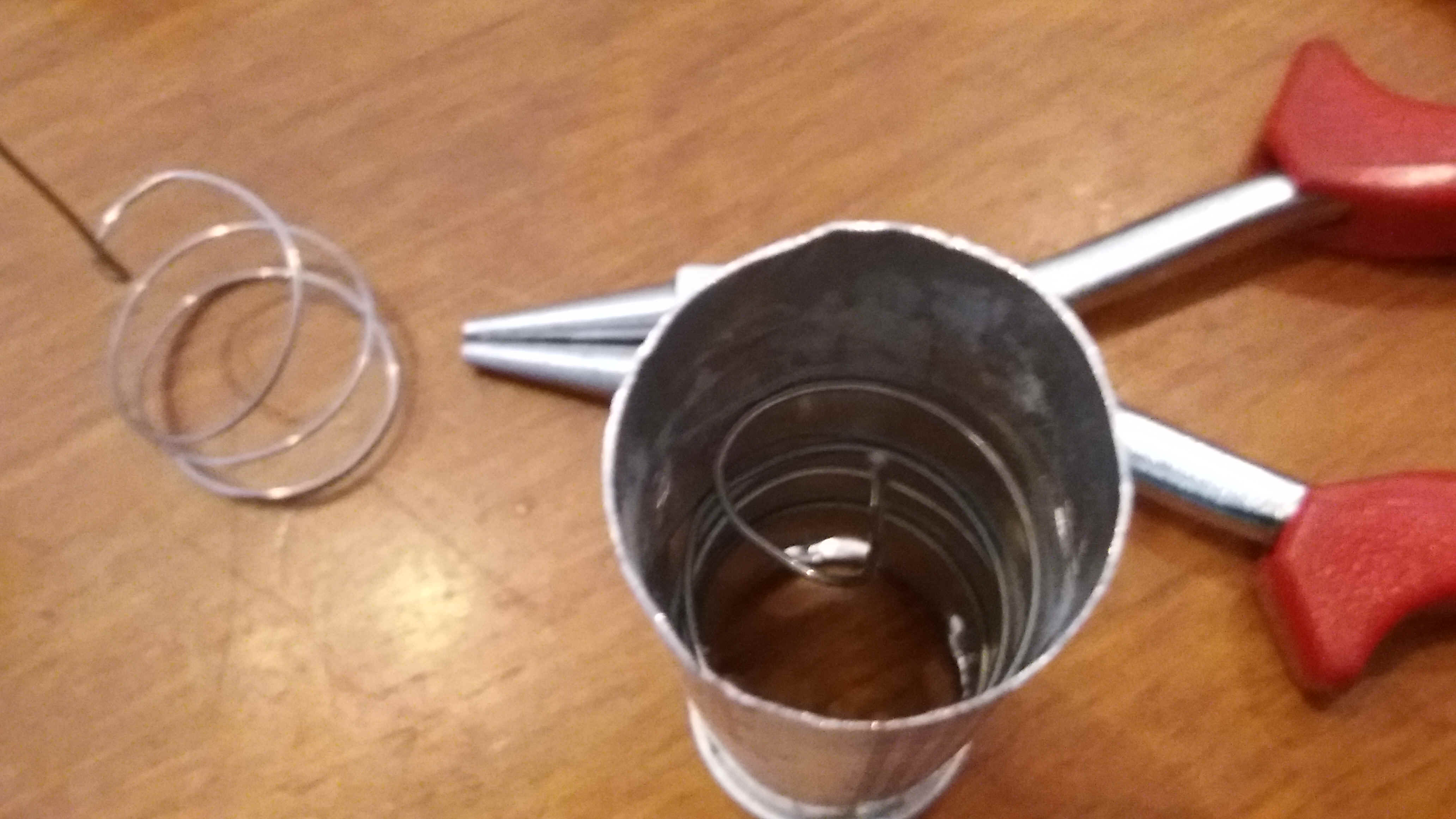
The above and below pictures shows the tools which I have used: wide and narrow flat pliers, needle nose and bent halve round needle nose pliers, and wire cutting pliers. A range of files: a flat rough file for cutting the bottom of the tubes, A fine halve round file, a fine flat file, and a very fine flat file to sharpen the rotor bearing end of the steel spring. An awl tool is shown next to the scissors, both used to pierce and cut aluminum. A felt marking pen is used for preparing the rotors 5) and the light shades 8). A meter is of course also necessary. A vice is shown under 2).
.jpg)
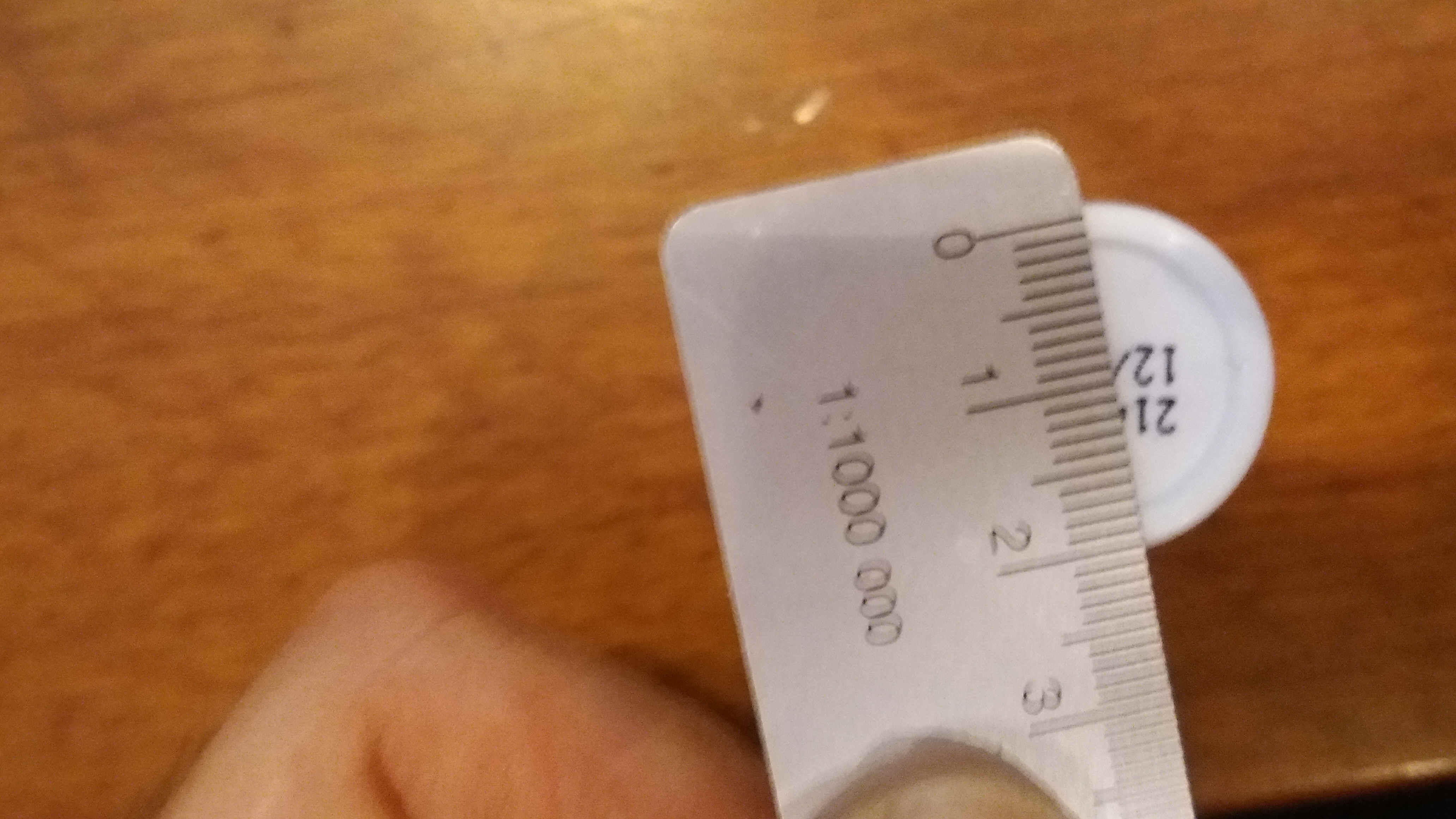
The following picture shows the templates used for building the ECANDLES. From left to right one can see a plastic tube which has been made by turning a piece of plastic foil of 4cm by 10cm, around a Supradyn tube and taping it in to a tube. The exact positions of the 4 holes, 5mm from the bottom edge, and evenly distributed around the Supradyn tube, are marked on the plastic tube and pierced with an awl. This template allows thus to mark and awl pierce the centers of the four air holes.
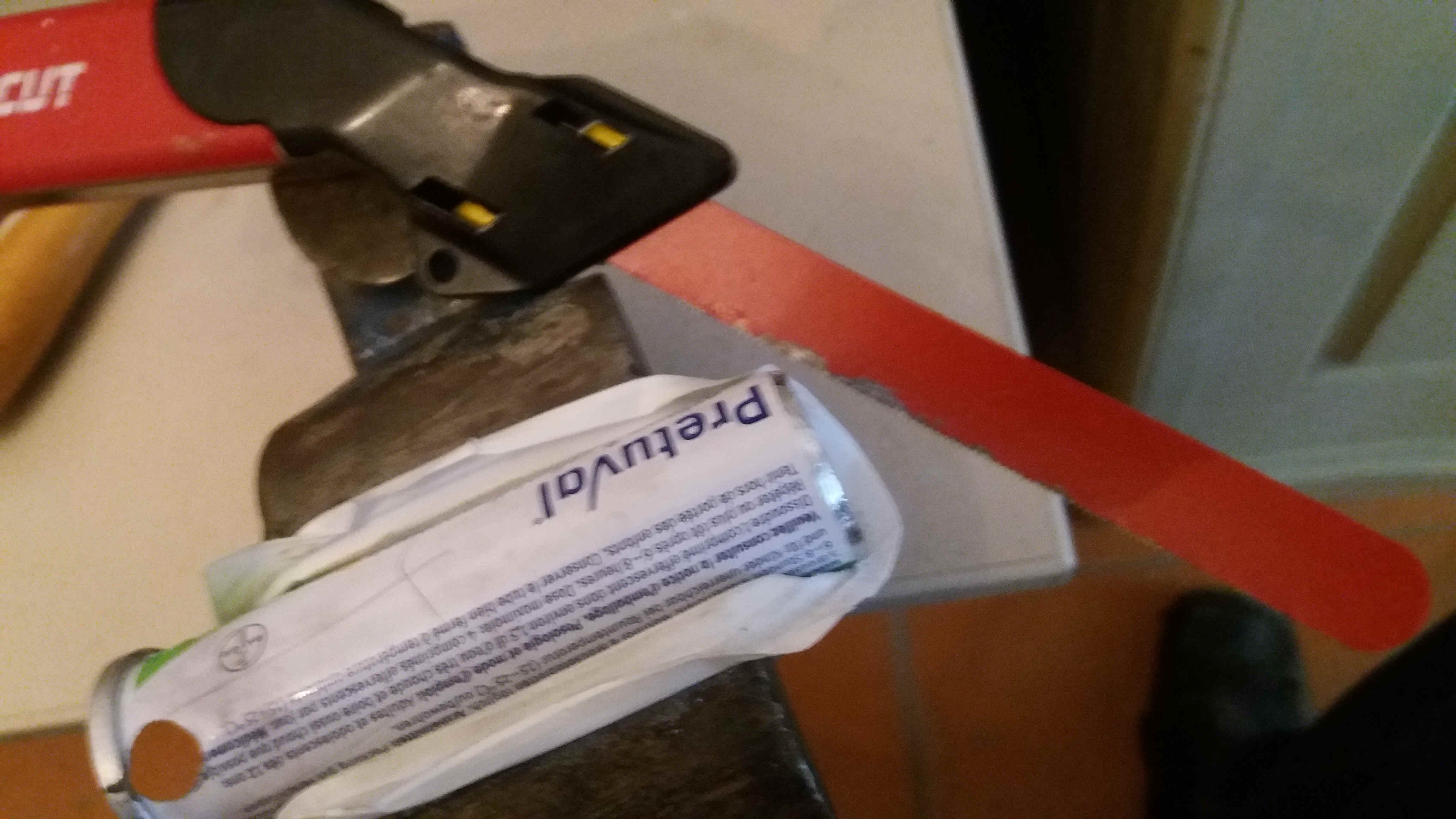
2) Cutting the bottom of the effervescent aluminum tubes
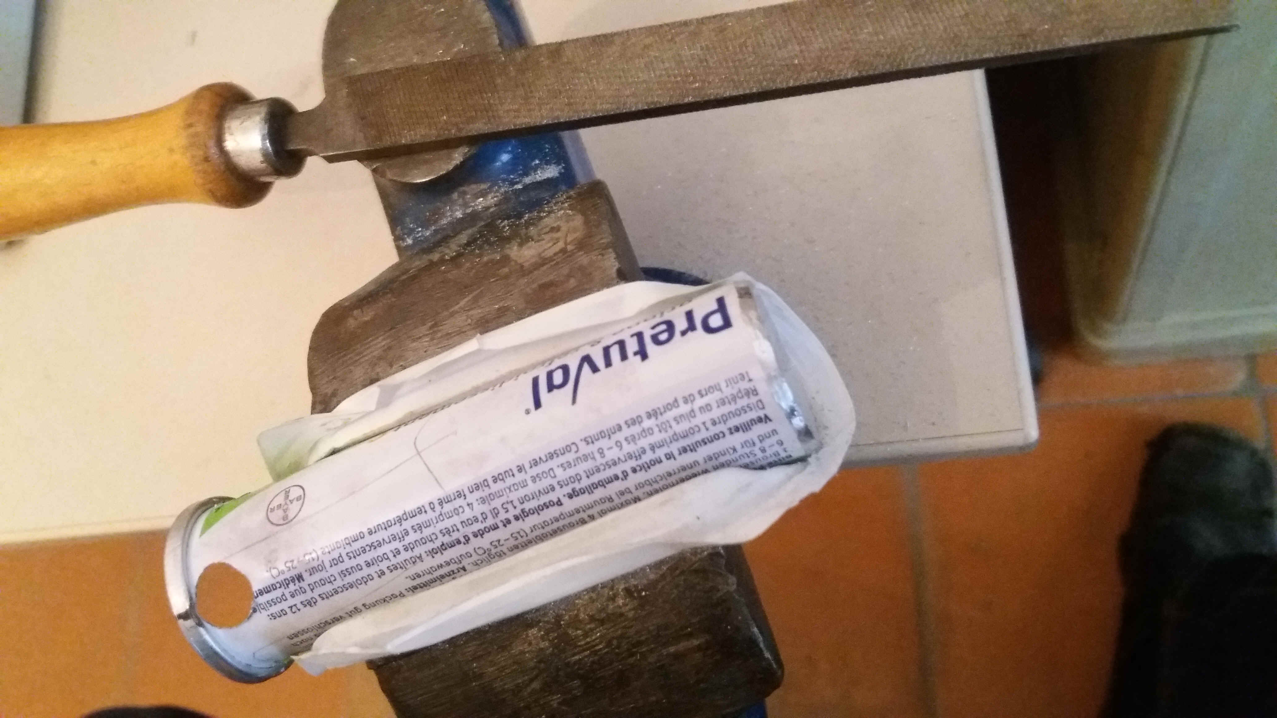
In order to cut the bottom of the tubes, the bottom edges are first limed all around the tube with a medium course file (see left above image) to form a ridge of about 2mm. A plastic cover is used to prevent from hurting the tubes by the vice. The bottom left picture shows that the bottom is cut within this ridge – the saw does not touch the yellow part. After each with of cut as shown the tube is turned for the next equal section. This careful approach is continued all around the tube until the bottom falls off.
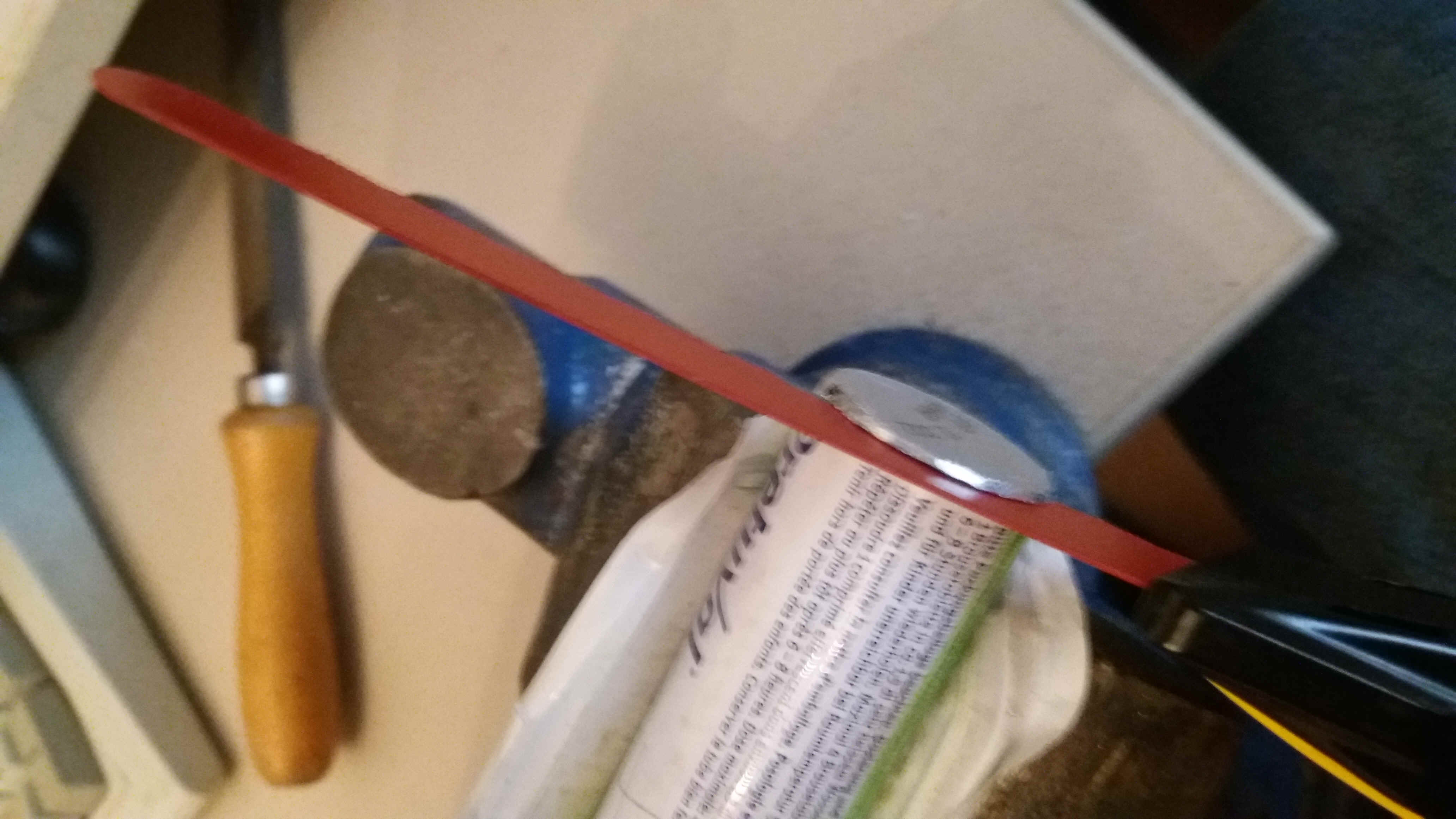
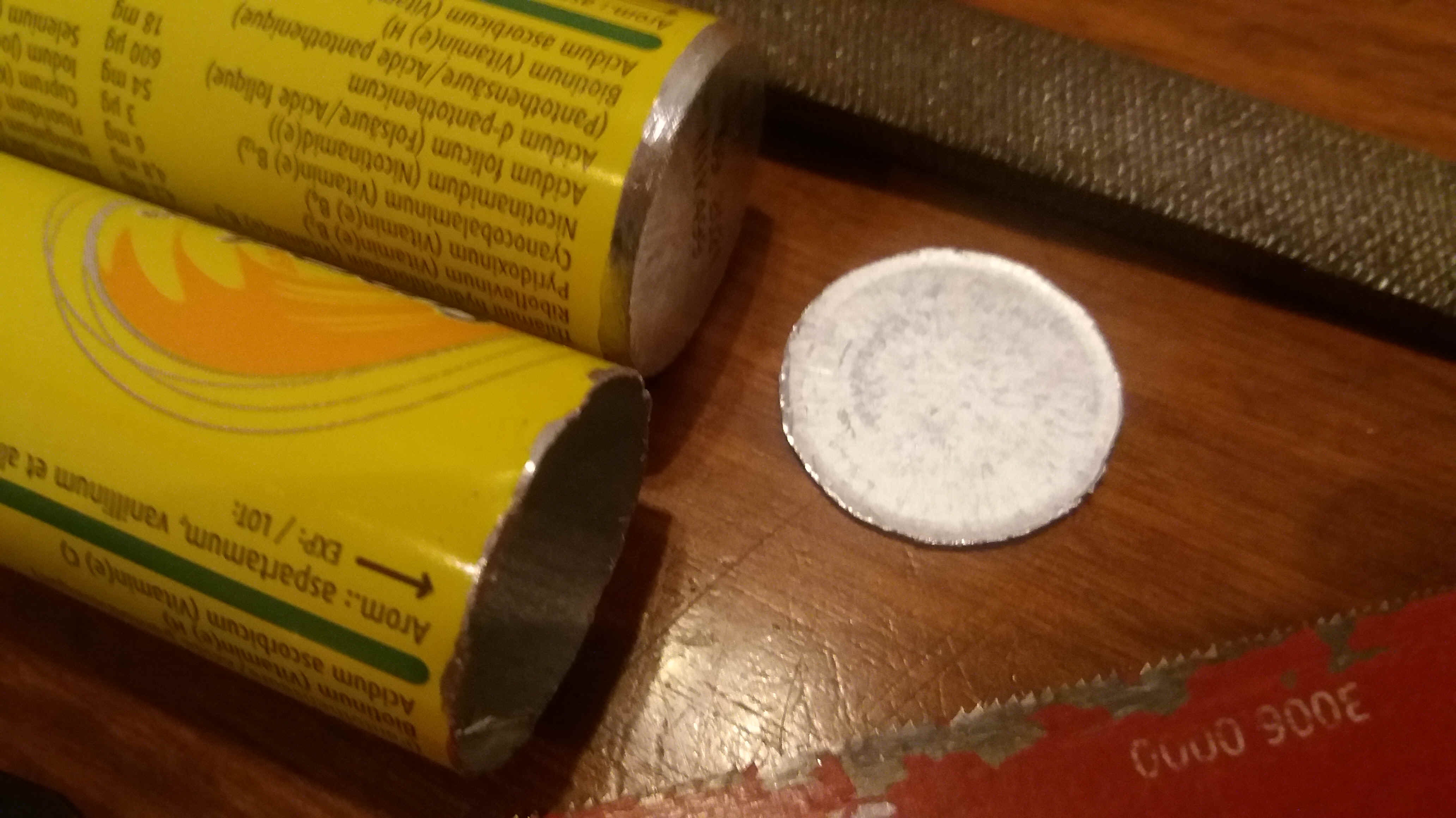
The top right side picture shows that an optimum cut can be done in this fashion
shown by the fact that the cut is exactly aligned with the top of the aluminum
bottom. The cut must finally bee made smooth and without cutting edges using a
fine semi round file, serving both in and outside the tube. Beware of cutting
edges - cut aluminum foil can be hideously sharp!
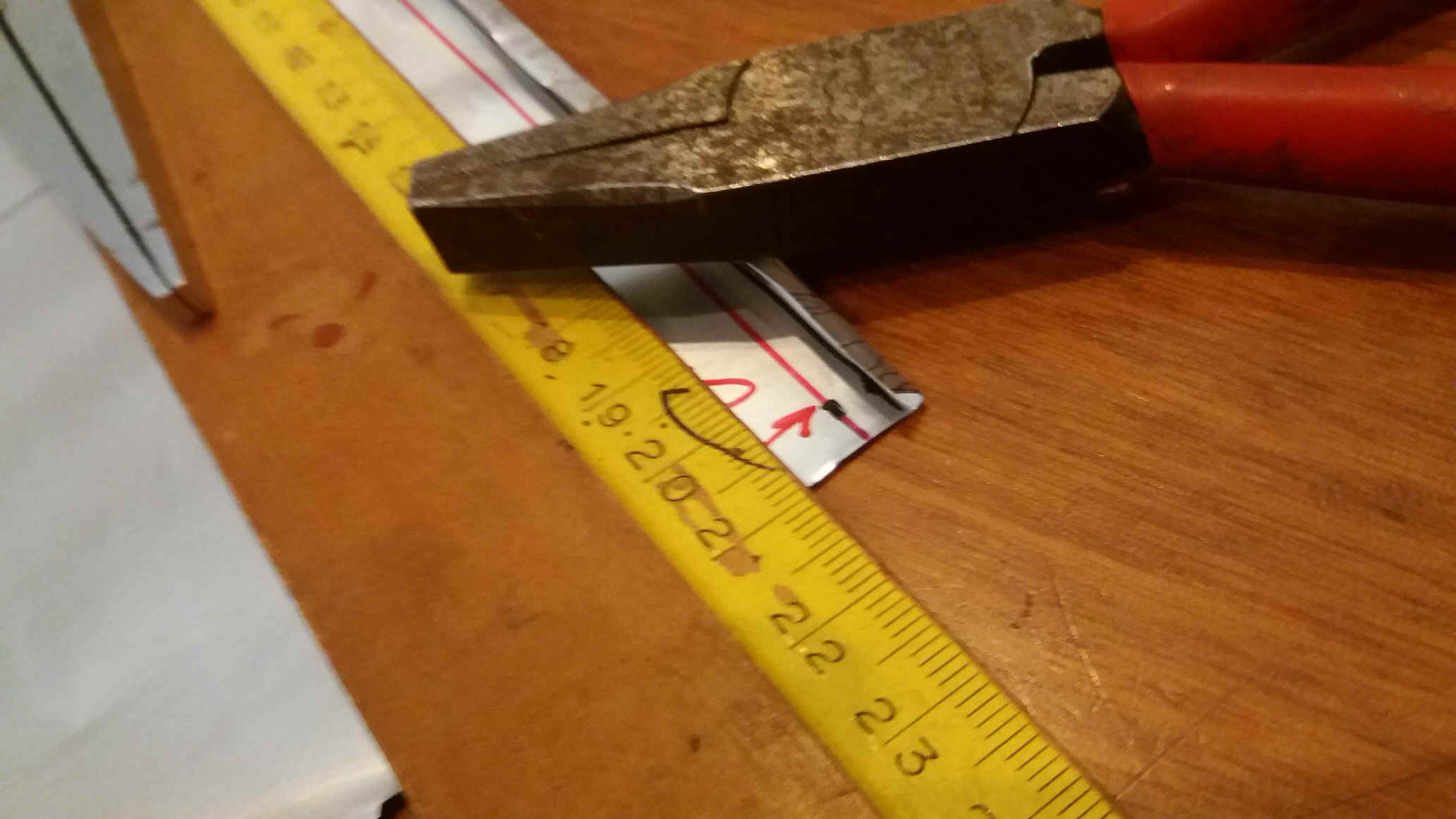
In case you do not have finished aluminum tubes of around 134mm length by 28mm diameter (i.e. Supradyn by BEYER), you can also make this tubes by wrapping aluminum foil from beer cans around a polymer packing of around 140mm by 28mm diameter (i.e. Vitamin C packing
by ALDI)
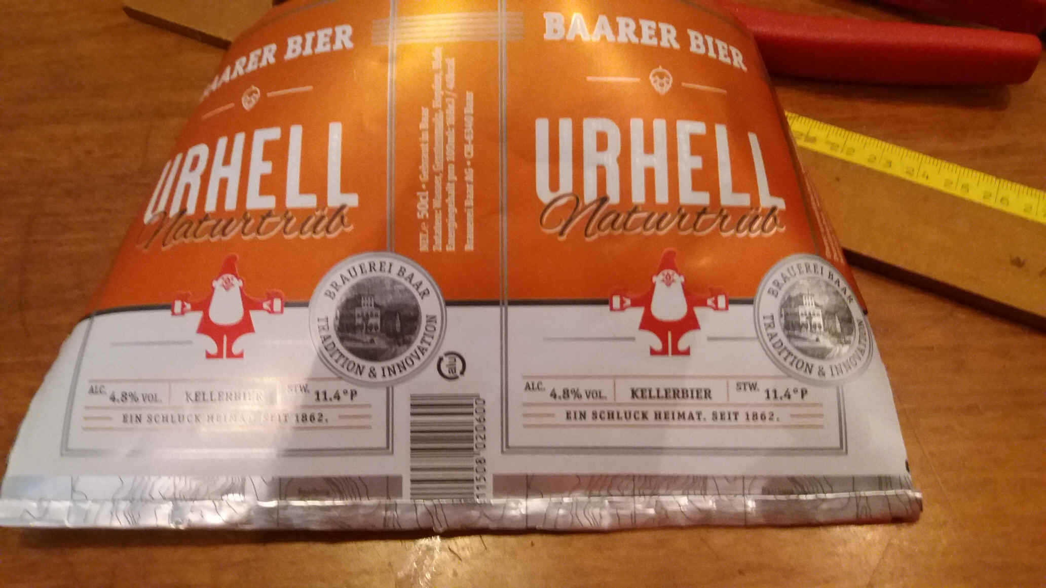
You first have to cut open the beer can with a scissors. Be carful not to cut yourselves on the aluminum foil! A normal standard European beer can will permit you to get a flat sheet of 14 to 15cm by about 21 cm.
We will cut this into to halves of 10.5 cm by about 14.5cm. We mark a line at 13cm (red) and wrap around the remainder with pliers to form a ridge at the bottom of the tubes.
Next we have to wrap each halve around the plastic core and fix the foil tightly with tape. The ridge also helps to fix the foil by gliding the closed part on one end into the open part on the other side and then by closing the ridge tightly using pliers. The cutting end of the tube is protected sticking tape around it.
Then folding the tape over the cutting edge.
3) Drilling 4 air holes into the tube on the end which is now the bottom of the ECANDLES
We want to place 4 1cm diameter air holes all around the tubes, touching the aluminum reinforcing ridge of the tubes. This permits to place these air entries in the neck region between the metal and the glass part of the light bulbs. This is optimal in order to cool the lights and transport of the thermal energy as hot air.
To this end the plastic hole template is pushed over the tubing and scotched to the tube in order to prevent it from moving while piercing the tube 4 times with an awl. Push the awl into the tube at a minimum, in order to just pierce it without widening the holes of the template. After this remove the template and carefully widen each hole by constantly turning the awl. Be careful as a sudden piercing can lead to an of center hole! Alternatively the holes could also be widened by using a hand drill as shown on the bottom left picture.
I widen the holes, by using all of my drills by hand, one after the other, from 3.5mm to 10mm.
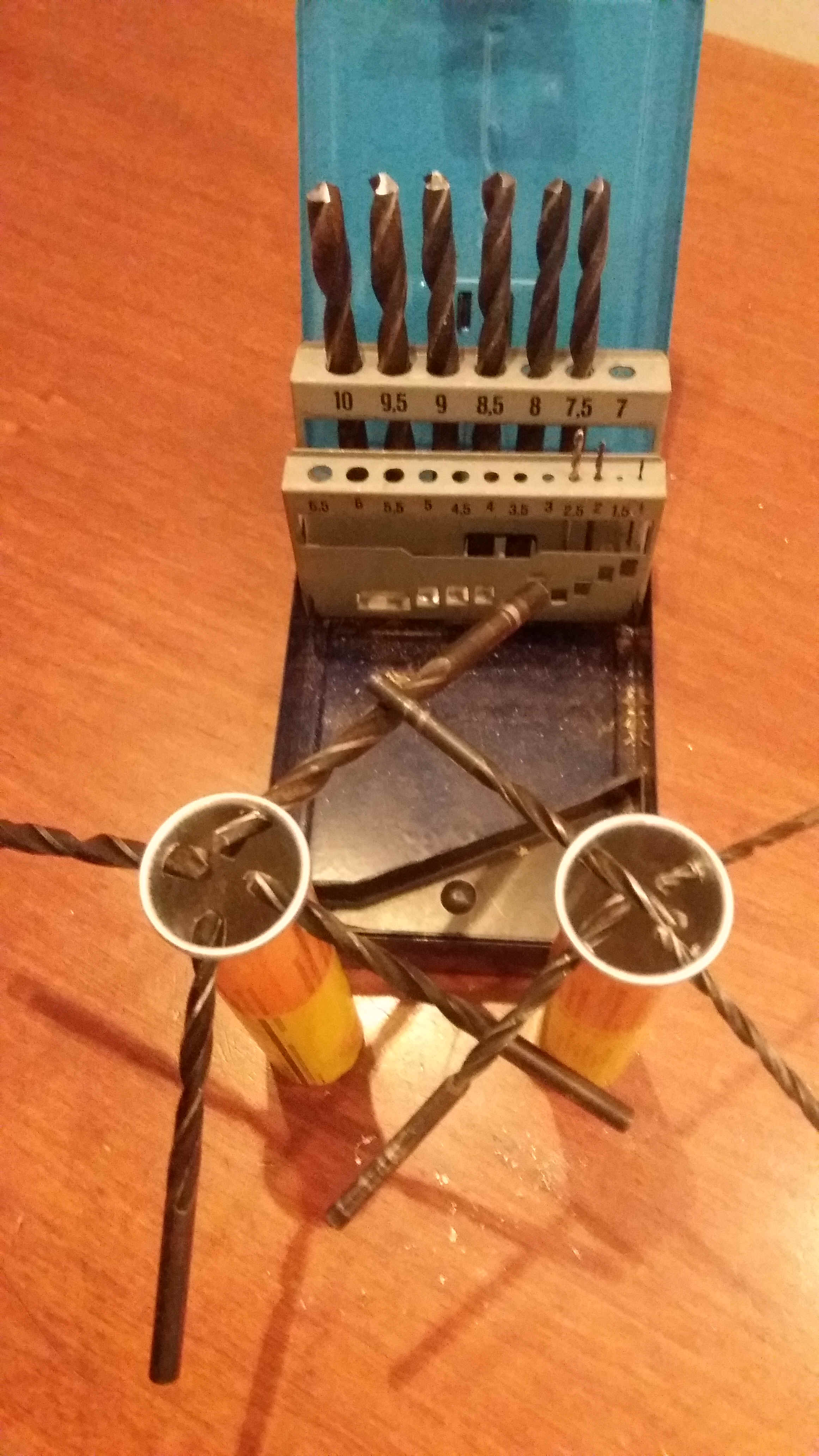
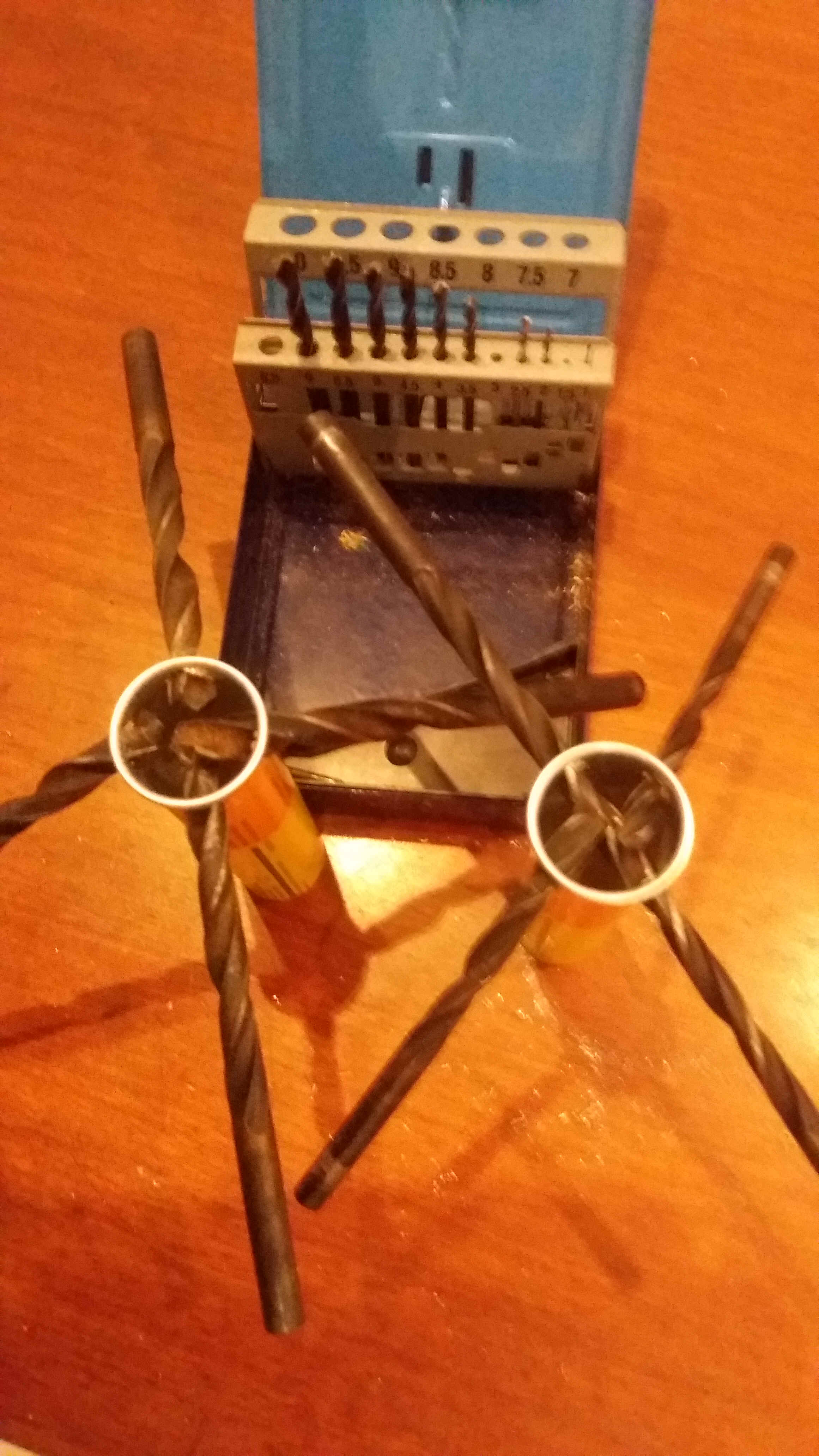
Of course I tried to drill using an electro drill, but noticed that in view of the soft material, which tends to tear out, the best results were achieved by the more tedious hand approach.
4) Winding, centering and sharpening of the turbine holding springs.
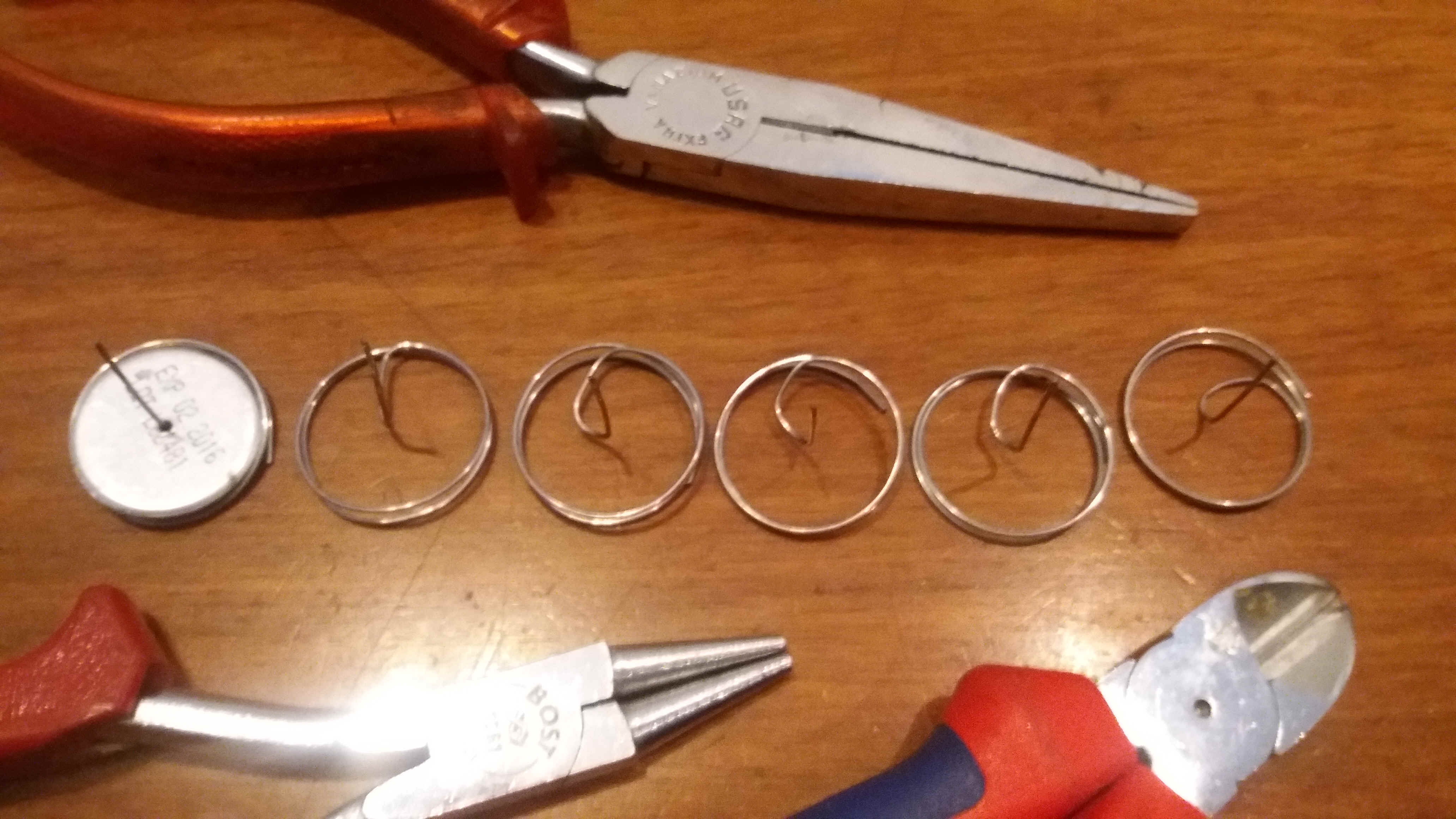
The hot air driven turbine contains a male part of a jeans rivet and this rivet in turn resides on a sharpened end of a stainless steel spring. The sprint effect blocks this piece inside the ECANDLE tube. This in turn insures that the straight end which is upwards bent in the center of the spring is solidly placed on the central axis of the ECANDLE.
A template tube of 2cm diameter is used to wind the spring. A 25cm overall length of a 1mm gage stainless steel wire is sufficient to form a spring piece. The first 25mm must be straight and are to the left (see lowest row left picture above) using the broad side of a needle nose pliers. The wire is then turned a second time at 30mm from the end to move the left looking straight end, away from you, by about 3mm (this second turn is also visible in the same picture above). This end is now pushed through the hole of the cover of the template, in order to hold it in place, while winding up the wire around the template. The winding is done by turning the tube by two and a halve turns away from you, while pressing the wire solidly against the barrel and the rim of the cover. The above right picture in the middle row shows how the spring expands back after letting go the wire.
After pulling the wound spring from the template, the straight part must be placed in the center of the spring by the needle nose pliers. Make sure that the straight part points at a right angle to the winding along the axis of the spring as shown in the top left picture below. Use the bottom piece template which is awl pierced in the center to verify the central position of the straight needle as shown top row right picture below. Place the spring inside an ECANDLE and again center the upper extremity of the needle using the same template (see middle row below).
Having cut the wire with a diagonal cutter the end of the needle has the shape of a roof. It must thus be sharpened carefully using a very fine lime as show above bottom left. Use very fine polishing paper and polish the needle all around. The effect of liming all around the needle should be checked with a magnifying glass (not mentioned above). Carefuly inspect the needle, while slowly turning it under the magnifying glass. For adjusting the spring a shortened tube is used, which allows to hold the spring wire while bending it to the center using a pliers.
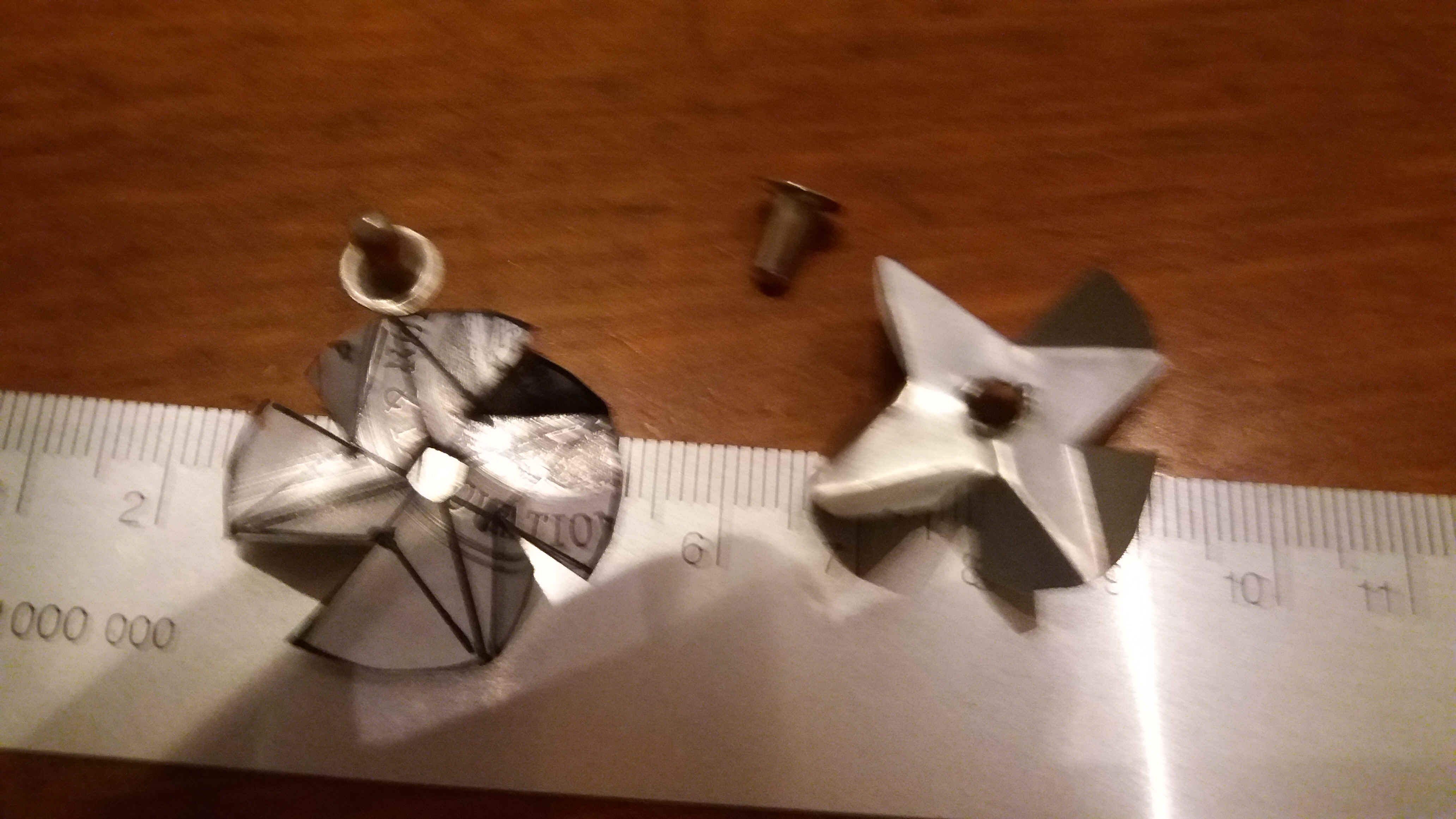
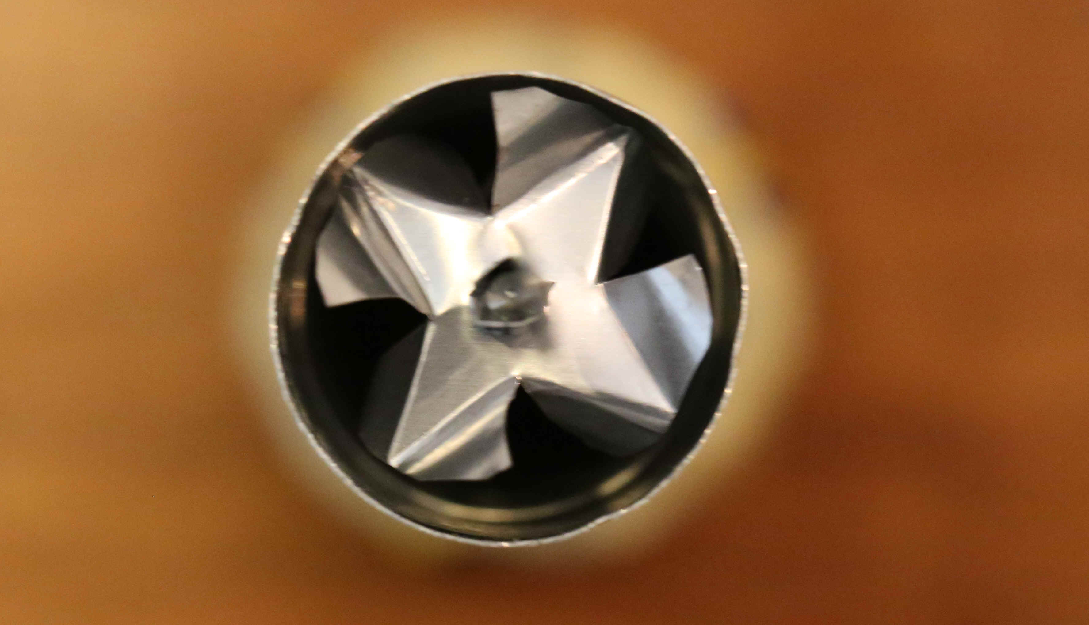
5) Cutting and forming the rotor
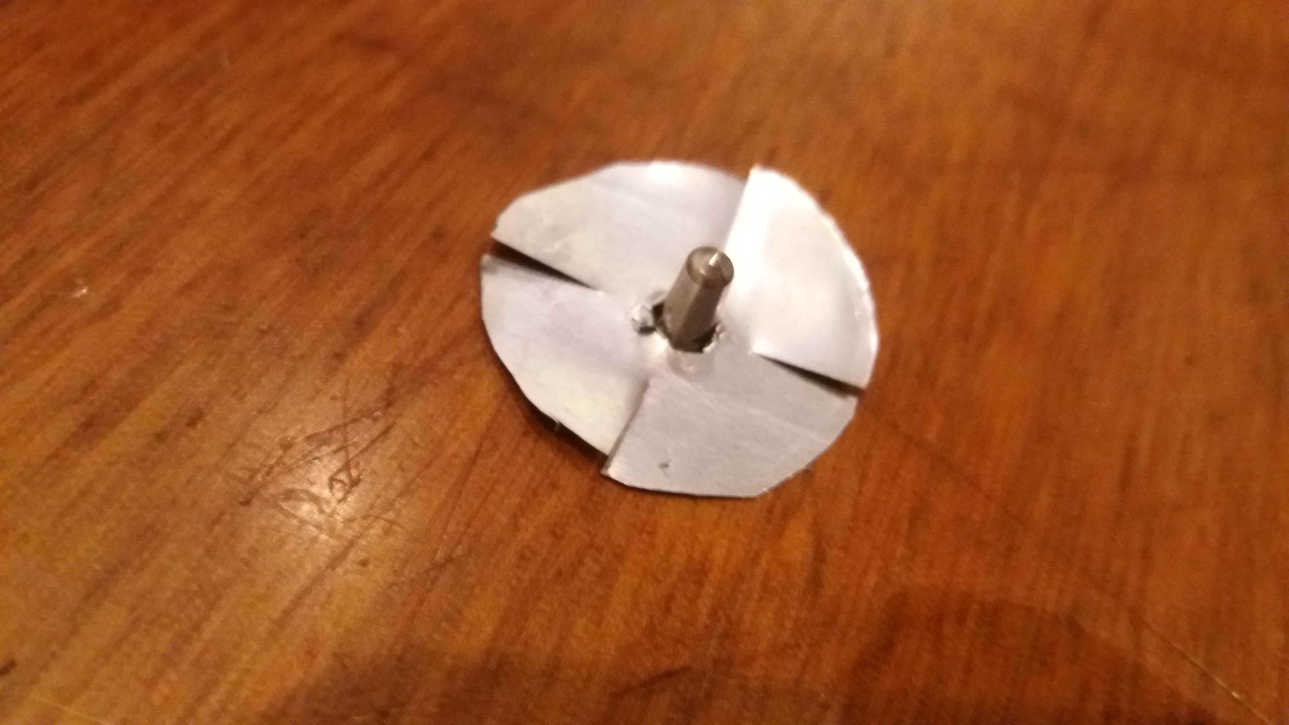
The bottom template with the star drawing is placed on the aluminum sheet cut out of a soft drink / beer can and with the awl the center point is punched in and the 8 circumference points are copied to the sheet. The central square and the star are then copied as well as shown in the bottom left figure above. This piece is then cut out with the scissors. The central hole is carefully enlarged with an awl and finally by pushing the sheet over a jeans rivet. The four cuts indicated by the cross are then made. Be careful to leave enough material around the rivet in order to not damage the rotor. Flip over the disk as shown on the left top image below and Bend the blades along the drawn lines of the star. Bend the 4 blades which point to the bottom (left picture below) and then the 4 blades which point to the top (right picture below). Note that a regular flat star should remain untouched.
.jpg)
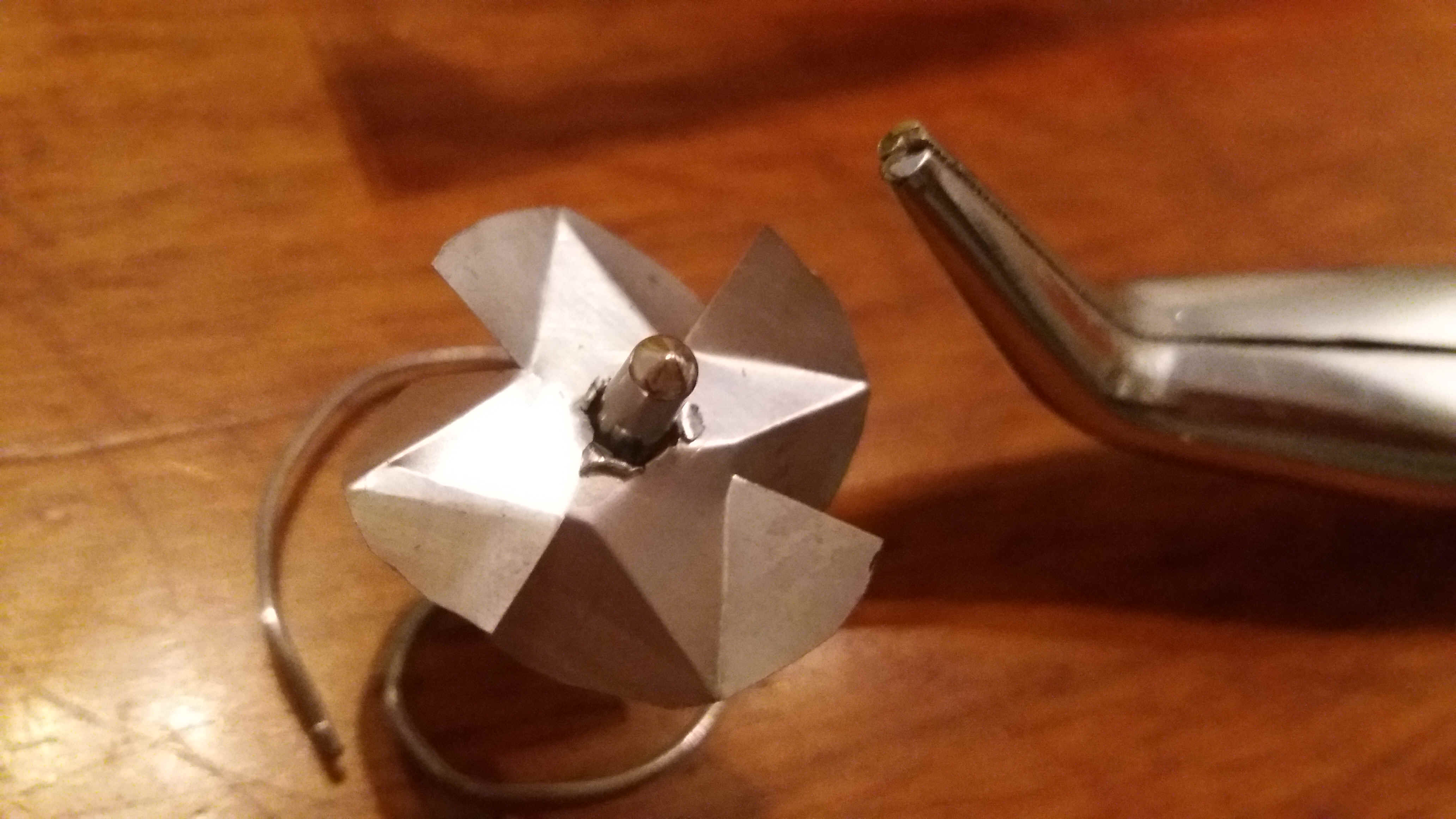
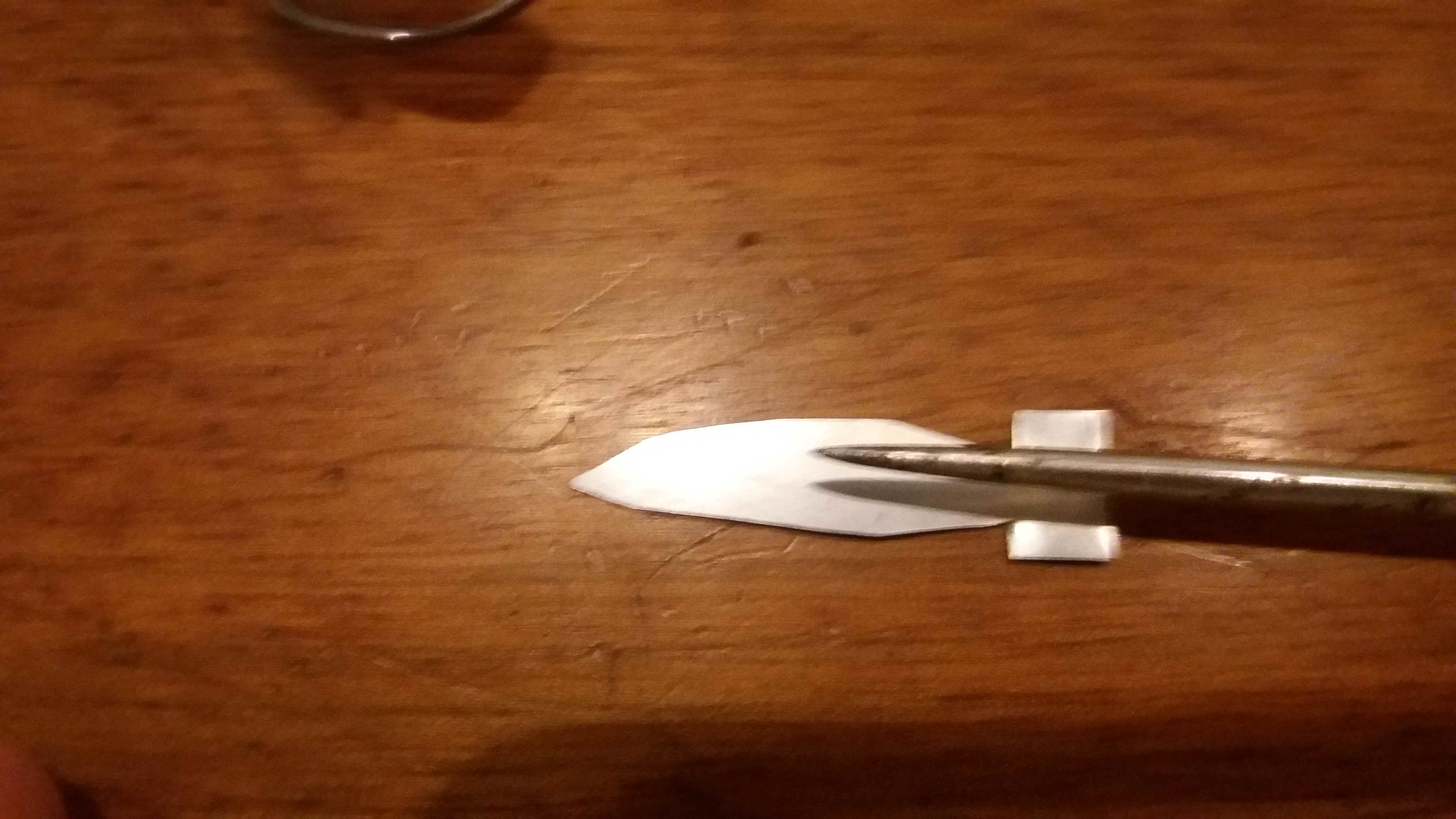
6) Gluing the flame on a jeans rivet on top of the rotor and fitting the rotor to the tube
Using the flame template trace a flame on the aluminum sheet (35mm overall height x 10mm overall with) and cut it out. The bottom part of the flame is twisted around the awl as shown on the pictures below. A drop of rapid 2 component epoxy is mixed and put on the rivet rotor assembly,
which in turn has been placed on the rotor spring piece (picture right bottom above). The flame is then firmly pushed onto the rivet in order to consolidate the rotor construction.
Once the glue has well hardened on has to balance out the rotor and fit it into a ECANDLE tube equipped with a well centered rotor spring. In most cases some rotor blade must be slightly trimmed with the scissors. Keep in mind that cutting will also reduce the push of the rotor. Once the rotor fits into the tube and is freely rotating, the assembly must be tested using a light. For this I used a vertical light, by bending into the vertical a bent light equipped with the narrow light bulb screw. You might have to play around a bit to find the optimal bending angles of the rotor. Also check if the rotor is still well balanced after trimmings.
My experience is that it is difficult to get rotors to turn in 95mm long Pretuval tubes without light shade. Even without light shade rotors should rotate without problems in 135mm long Supradyn
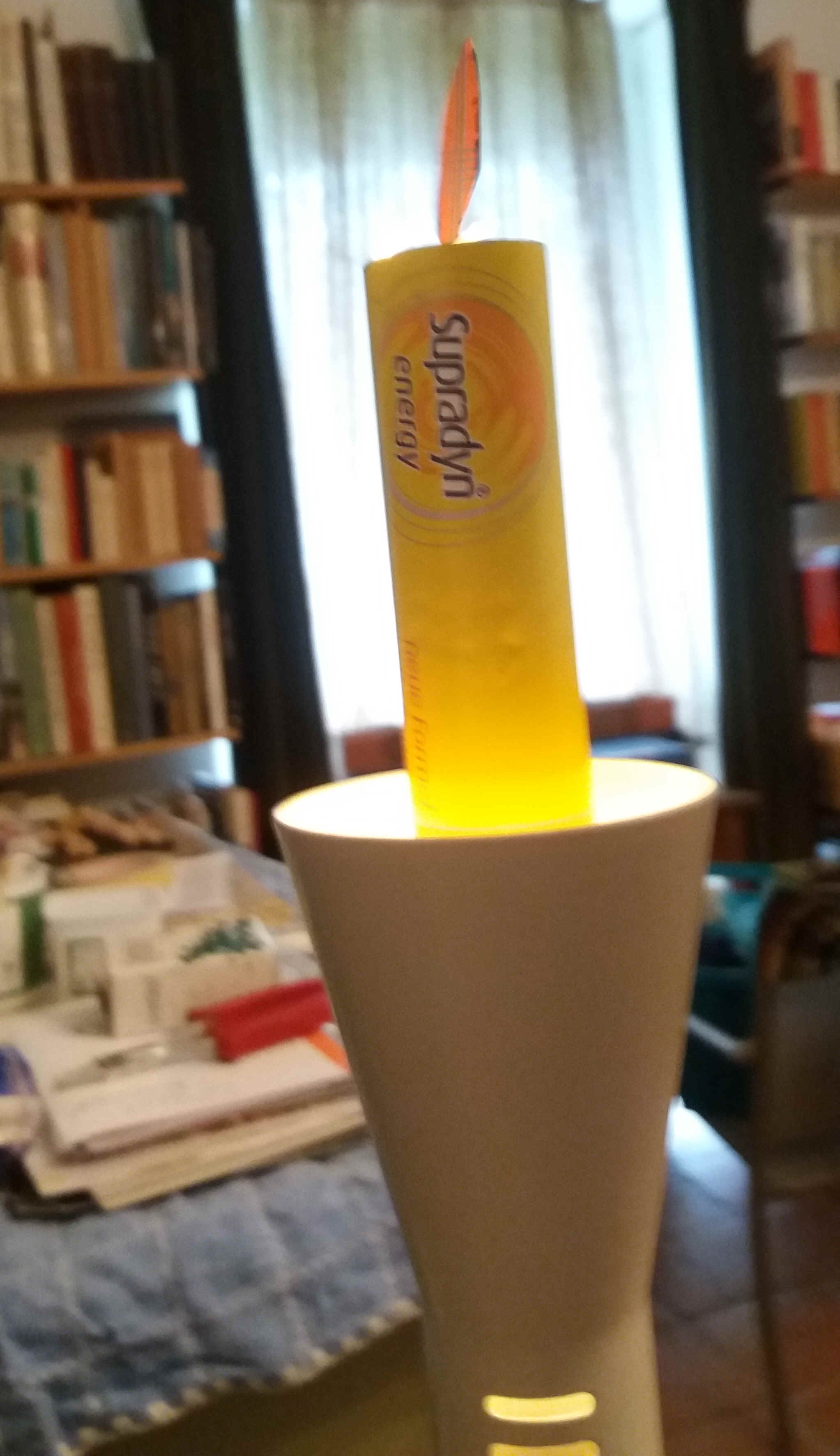
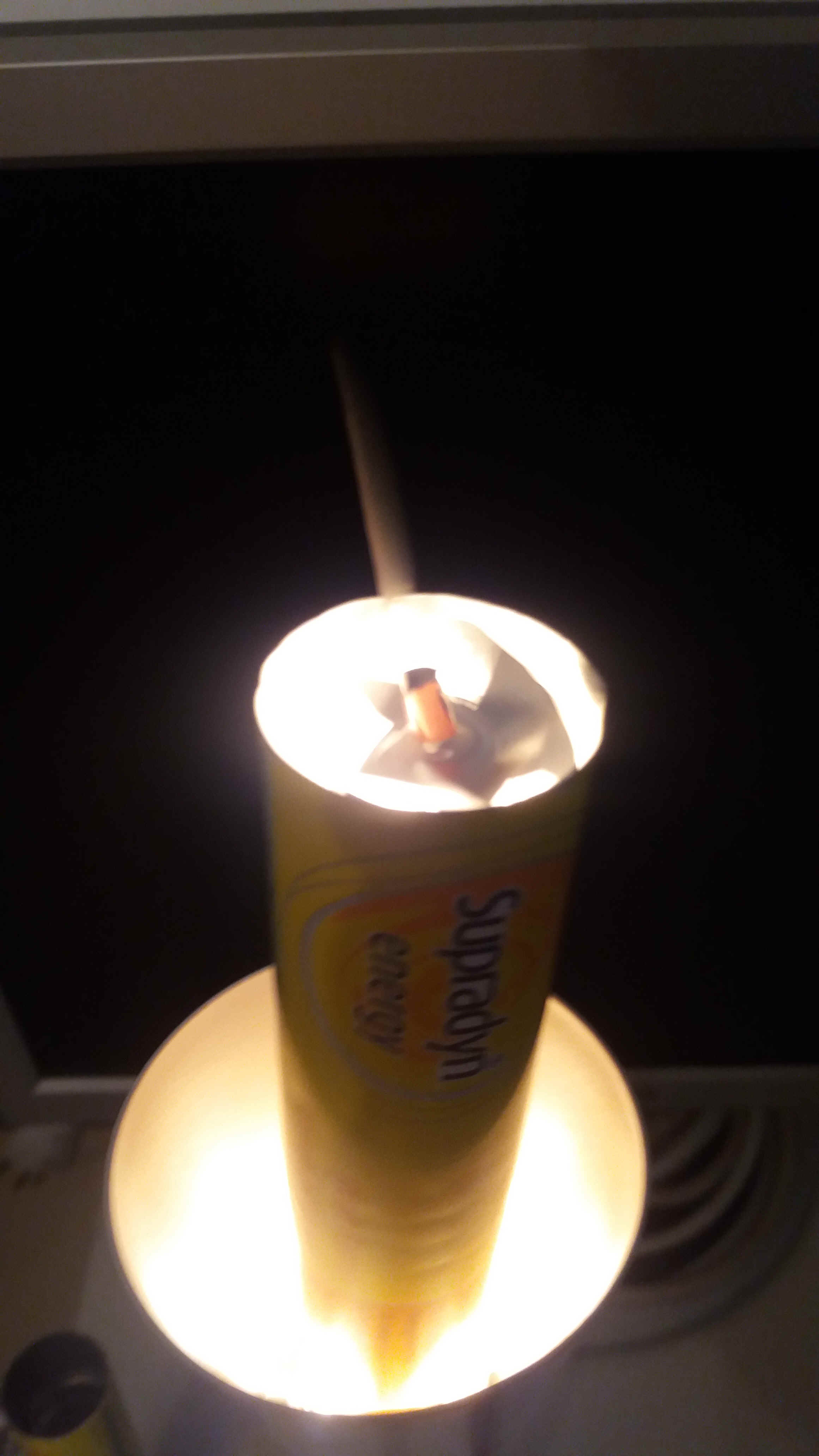
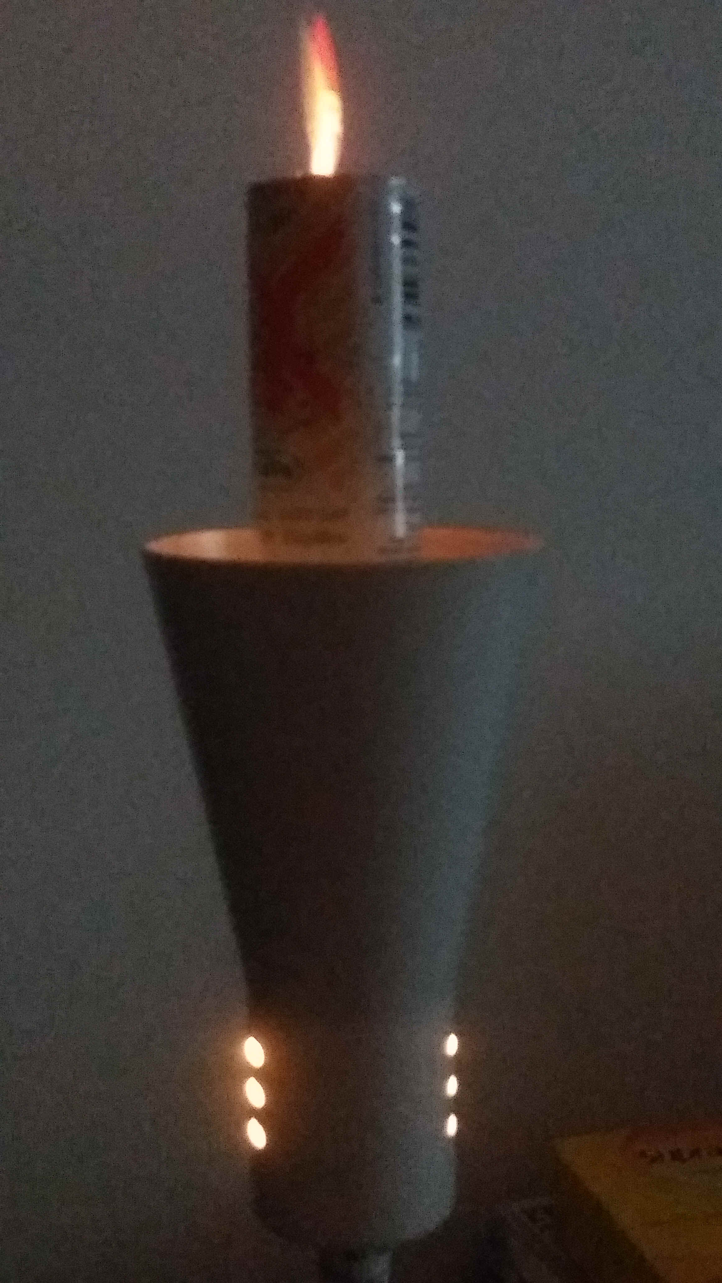
tubes. The addition of the light shades greatly helps to get a healthy flow of hot air into the rotor. The reason is that the whole tube heats up due to heat conduction of aluminum. This creates a heat flow also outside the tube which reduces the heat flow inside the tube. A light shade which is closed on top reduces the outside flow and leads to preheated air flowing through the four holes to the inside. The inside air flow is thus visibly enhanced. The above picture shows my testing setup equipped with long tubes (left and middle) and short tubes (right picture).
This setup is essential to allow correctly trimming and balancing out the rotors as shown in the following pictures. Please note, the rotor blades have now been bent from straight to round, above and below the plane of the rotor, with needle nose pliers. Also visible is the result of the trimmings. The balancing out is mainly done in the lamp setup shown above. If the rotors are off center The centrifugal forces cause the rotor to move of center on the needle of the rotor spring. This results in friction and / or touching of the blades with the hot air conduct wall.
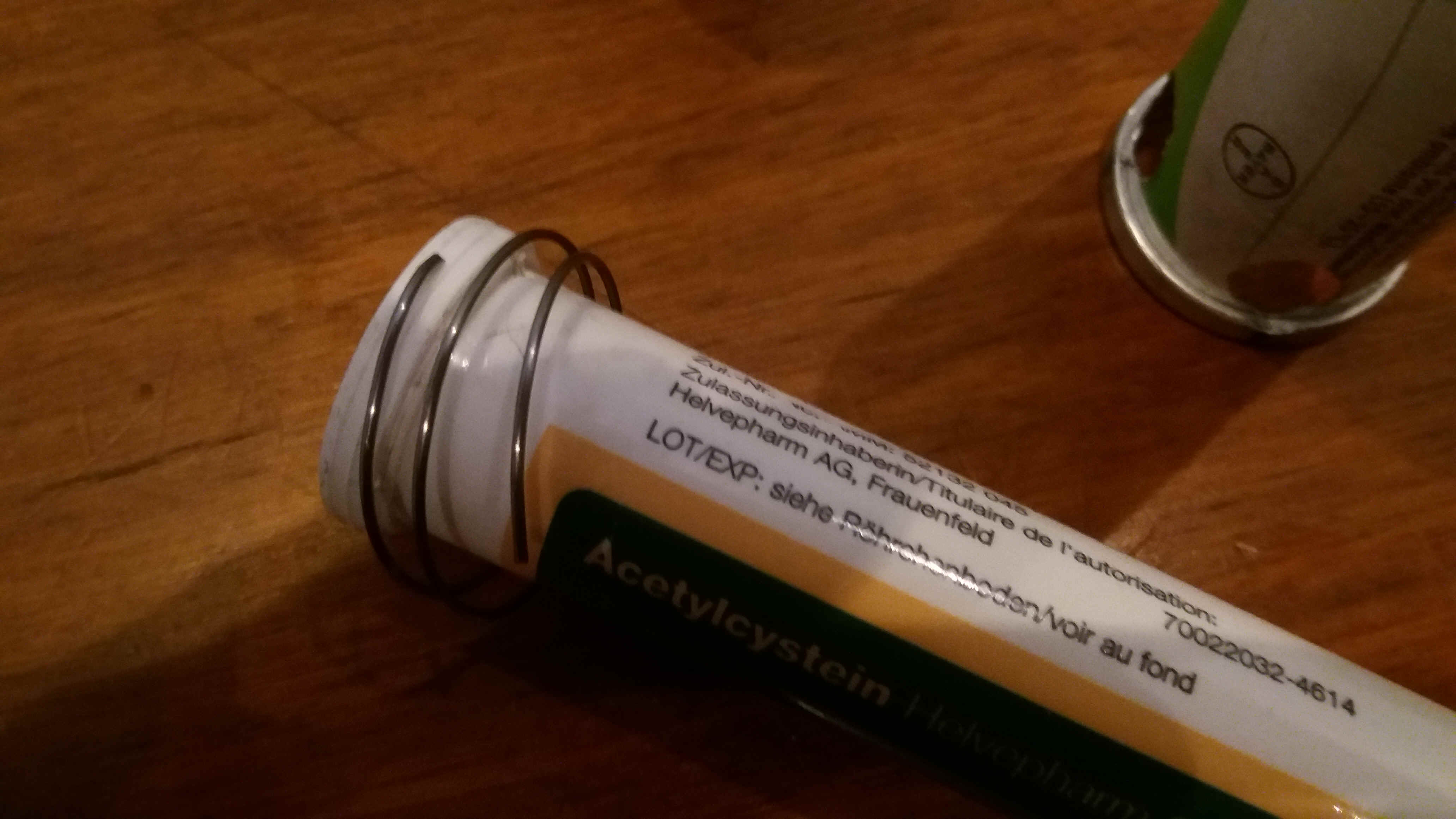
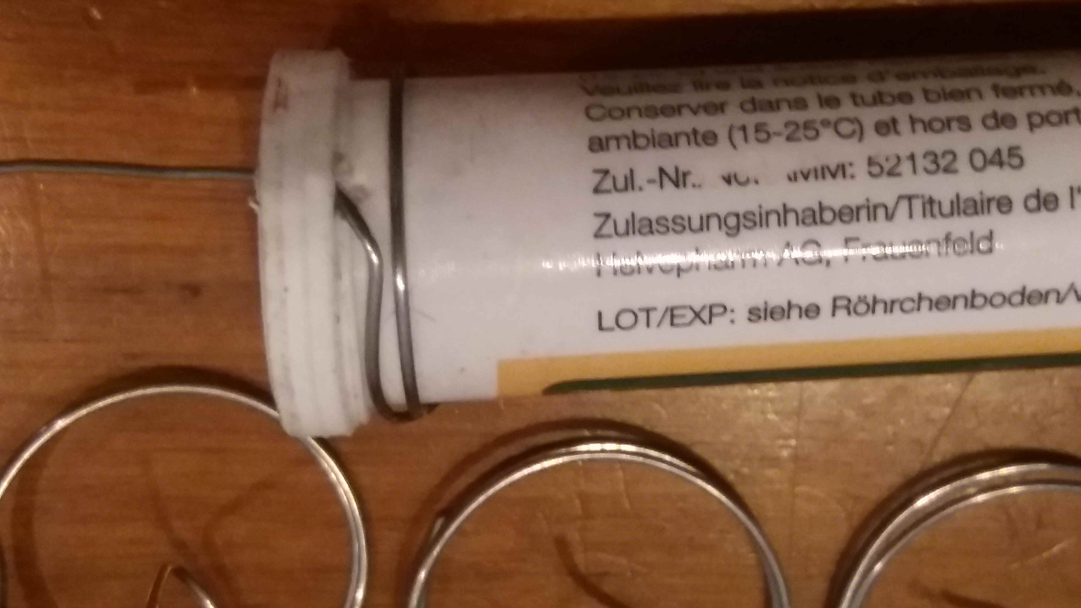
7) Wrapping a spring holder for the ECANDLES
Roughly 20cm stainless steel spring wire are wrapped by two and a halve turns around the 2cm diameter template. The upper end of the candle holding spring is slightly bent towards the inside of the coil (see left picture of top row above)so that it can be blocked in one of the air holes as shown by the right side Pretuval tube on the bottom figure above. Depending on your chandeliers you might have to make longer coils.
8) Building a light shade around the four air holes
The above and bellows pictures shows that I have played around with various alight shades. I include images for building them in case you can use or must use large size shades. These models are directly cut from small diameter soft drink cans, using the bottom or top parts.
A way to make narrower light shades using a spice vial as a template is shown here. Cut open a can by cutting off the bottom and the top with scissors. Start out by punching a hole on the edge of the top with an awl. Then carefully cut all around the top – mind the cutting edges! Then cut along side following the visible seam left by the printing of the can. Now you can easily cut of the bottom. You should land up with a sheet of 14 to 15cm by about 21 cm. In direction of the long side mark 4cm strips for cutting up the sheet. Also mark a line at 1cm, 5cm, 9cm, and so on, as shown on the right bottom image below. Finally cut the 4cm strips making 5 light shades using the scissors. Depending on your chandelier you can also cut 4x 52.5mm or 3x 70mm strips.
Using the 41mm diameter spice vial template wrap a foil around the vial having the 1cm distance line towards the inside and the bottom of the vial. Use masking tape to fix the foil and stick masking tape over the outside visible end and fold the outside part towards the inside. Do the same thing over the inside visible end of the overlapping foil, and this time bend the overhang
towards the outside as seen in the above pictures. Next you have to bend the foil 4 times towards the inside along the 1cm marking line using the bigger pliers. Finally use the finer pliers to fold in the rest all around the vial. Test the size of the hole using a candle tube (right bottom below).
Use masking tape all around the sharp edge to finish off the cone as shown below.
9) Final assembly, testing and painting the ECANDLES
Use a heat resistant white paint to finish the electric chandelier candles
MP4
MP4