ENGLISH:
The presence of a wind measuring tower is the key to a
simple graphical method for predicting the appearance of a wind farm in the
landscape. You will find here a simple procedure to produce reliable
syntheses of the relative heights and the spatial distribution of wind
turbines superimposed on digital pictures. Of course this synthesis will
be done on a computer using a good graphical software which integrates pixel and
vector graphics. For many years my personal favorite for this is
COREL PAINT and COREL DRAW. Wind measuring towers come standardized with
calibrated heights and well known positions in the landscape. In the present
case the tower is built up of each time 4 segments of a length of 3m and a
given color. In our case 7 sections of alternating red and white color are
used and the full heights of the tower measure thus 84 meters (/7x12m=84m).
The 84 meters correspond to the height of the axis of the planned wind turbines.
Please note that at least one full section must be visible on the picture in
order to construct a synthesis.
FRANCAIS:
La présence d'une tour anémométrique
facilite bien la construction des vues de l'impact visuel d'implantations
d'aérogénérateurs dans le paysage. Ici vous trouverez méthode pour
procéder par une simple méthode graphique, à la réalisation de synthèses fiables, en se servant de photos électroniques.
Bien sur tout cela se fait sur un ordinateur en utilisant un bon logiciel qui
permet de procéder avec des opérations dites pixel graphiques et de vecteur
graphiques. Personnellement je me sers de COREL DRAW pour cela. La
tour anémométrique est calibrée en hauteur et est de position précisément
connue. Elle est construite à partir de chaque fois 4 segments de 3m de
même couleur donnant en notre cas 7 sections de 12 mètres et mesure donc
quatre-vingt quatre mètres de hauteur pour les partie colorés en rouge ou en
blanc (7x12m = 84m). Les 84 mètres correspondent à la hauteur de l'axe des
turbines. Notez qu'il est essentiel qu'au moins une section de 12 mètre soit
visible sur la photo pour pouvoir faire une synthèse.
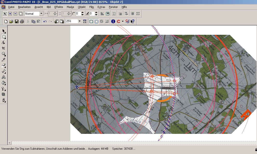
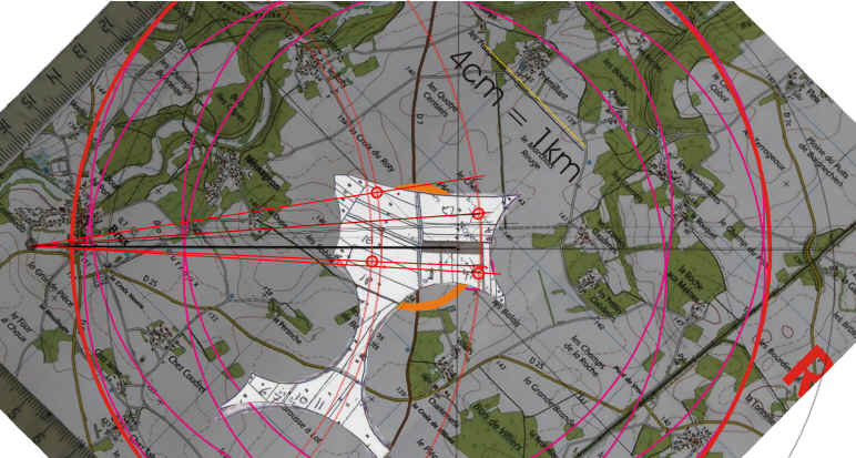
ENGLISH:
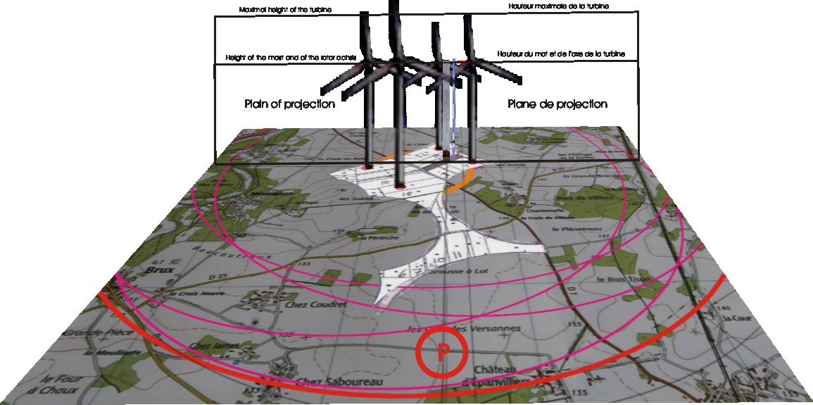
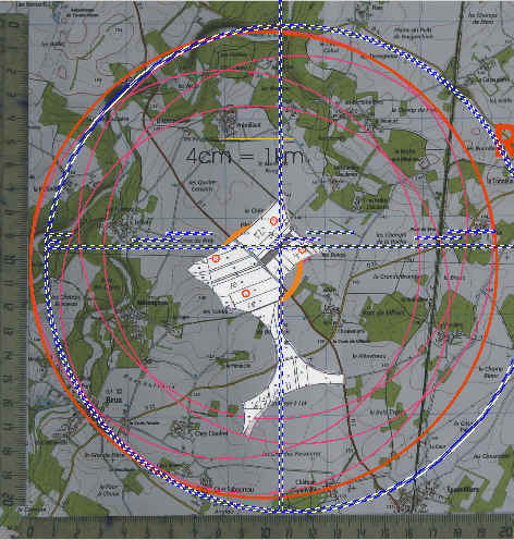
A template is used to start up any visualization of a given project for
which a wind measuring tower has been built up. Our plan show a 2
kilometer circumference around the RP-Globel project at Brux in the
southern Vienne in France. The position of each of the four
turbines is indicated as well as the position of the reference tower.
The template also contains a construction circle with the projection
plane as seen from above (a single line) and the construction plane
which has been flipped upwards, thus showing the three lines presenting
ground level, the heigth of the reference tower (84m = rotor axis
height) and the maximal height of a wind turbine.
|
FRANCAIS:
Un plan préfabriqué qui contient la région de 2 km autour du
projet RP-Global et indique le placement de chaque éolienne et du mat
de référence est ouvert, comme`` Template`` ci dessous pour réaliser une
construction. Un cercle de construction contenant le plan de projection vu de
dessus et du plan de construction vue de côté est aussi présenté.
Le plan de construction contient les trois lignes pour la base du pied
du mat, pour la hauteur du mat de référence, correspondant aux 84
m de hauteur de l'axe du rotor et pour la hauteur maximale d'une
éolienne. |
|
 |
ENGLISH:
A black line is drawn from the camera to the position of the reference
tower representing the line of view to the reference tower. |
FRANCAIS:
La ligne de vue de la caméra vers le pied de la tour anémométrique est
indiqué par une ligne noire. |
|
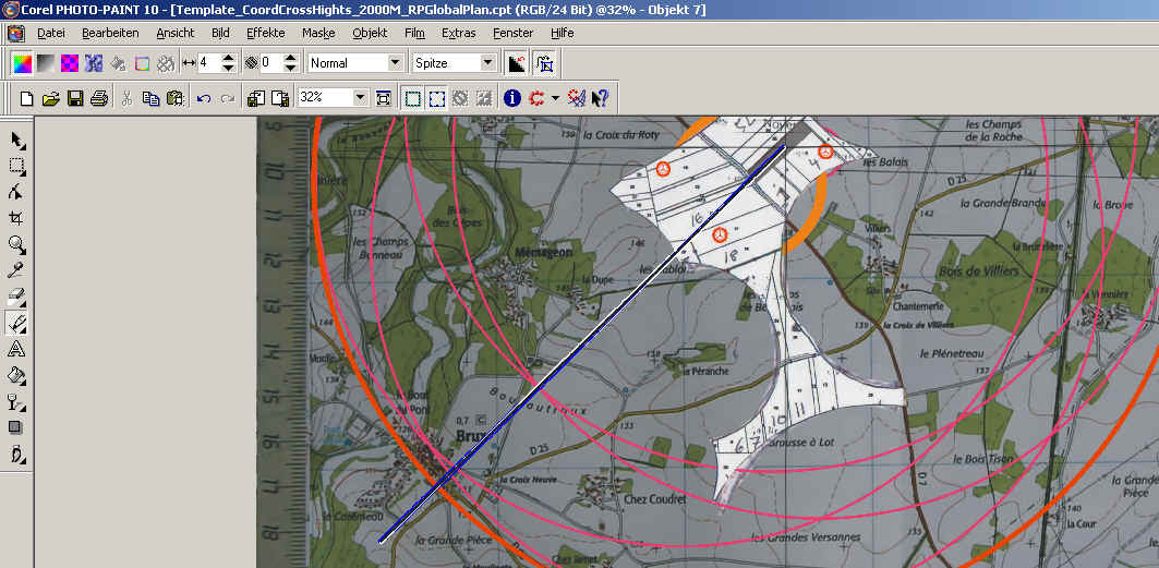 |
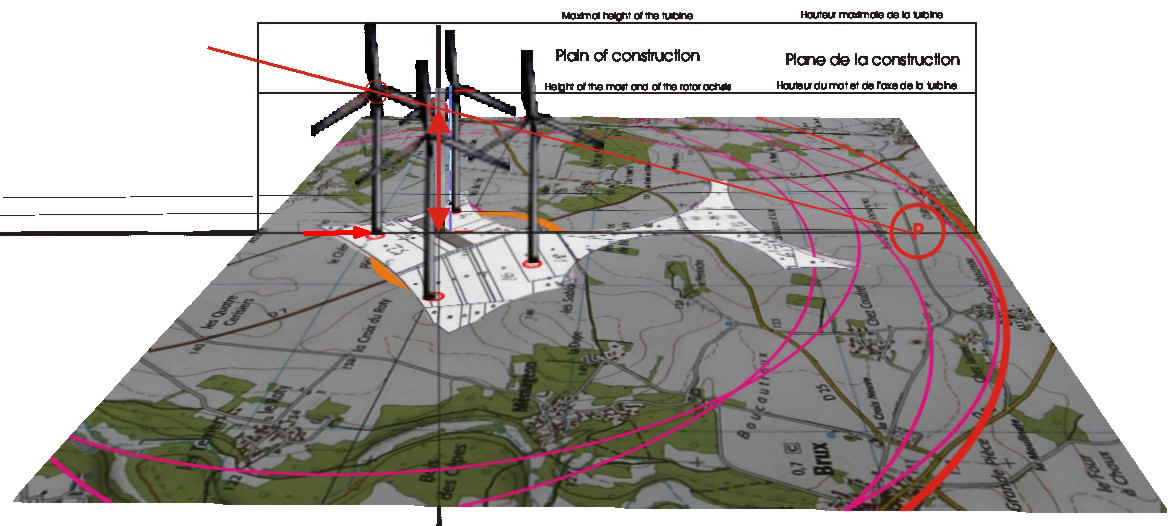
ENGLISH:
The assembly of the construction circle with the projection plane and
the construction plane is now turned around the reference tower position
in order to align the base of the construction plane with the black line
of view. |
FRANCAIS:
Le cercle de construction contenant le plan de projection vue d'en haut
et du plan de construction vue de côté est maintenant tourné autour du
pied du mat pour amener la base du plan de construction sur la
ligne de vue de la caméra au pied du mat de référence. |
|
 |
|
 |
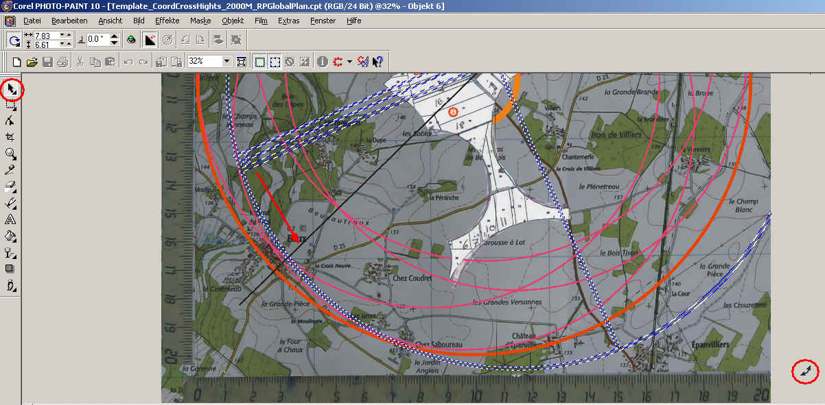
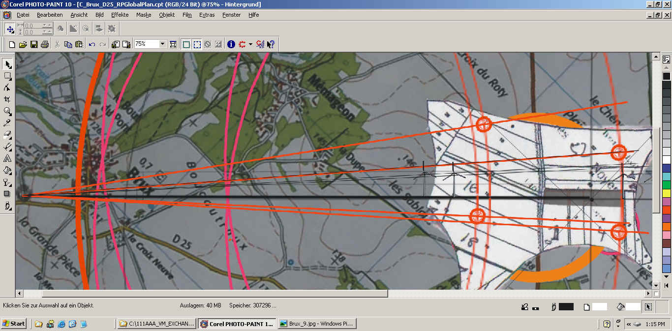
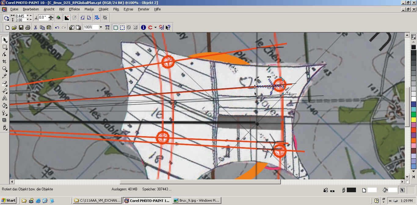
ENGLISH:
The whole image of the map including the construction circle is now
turned in order to bring the base of the construction plane back into
the horizontal. |
FRANCAIS:
Toute l'image de la carte et des ajouts de construction sont tournés pour
amener la ligne de vision à l'horizontale. |
|
 |
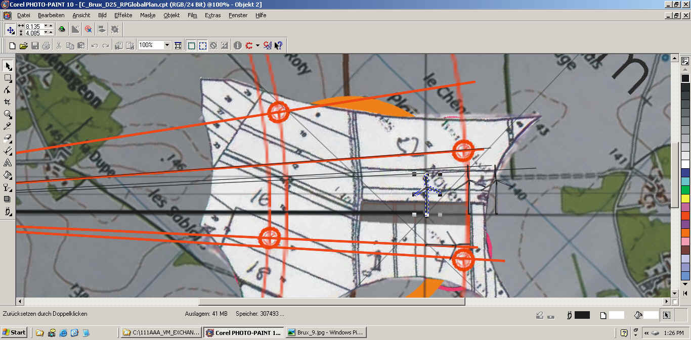
ENGLISH:
Red lines are now drawn from the camera position to the position of each
wind turbine. |
FRANCAIS:
Des lignes rouges sont introduites pour chaque ligne de vision de la
caméra à chaque pied d'éolienne. |
|
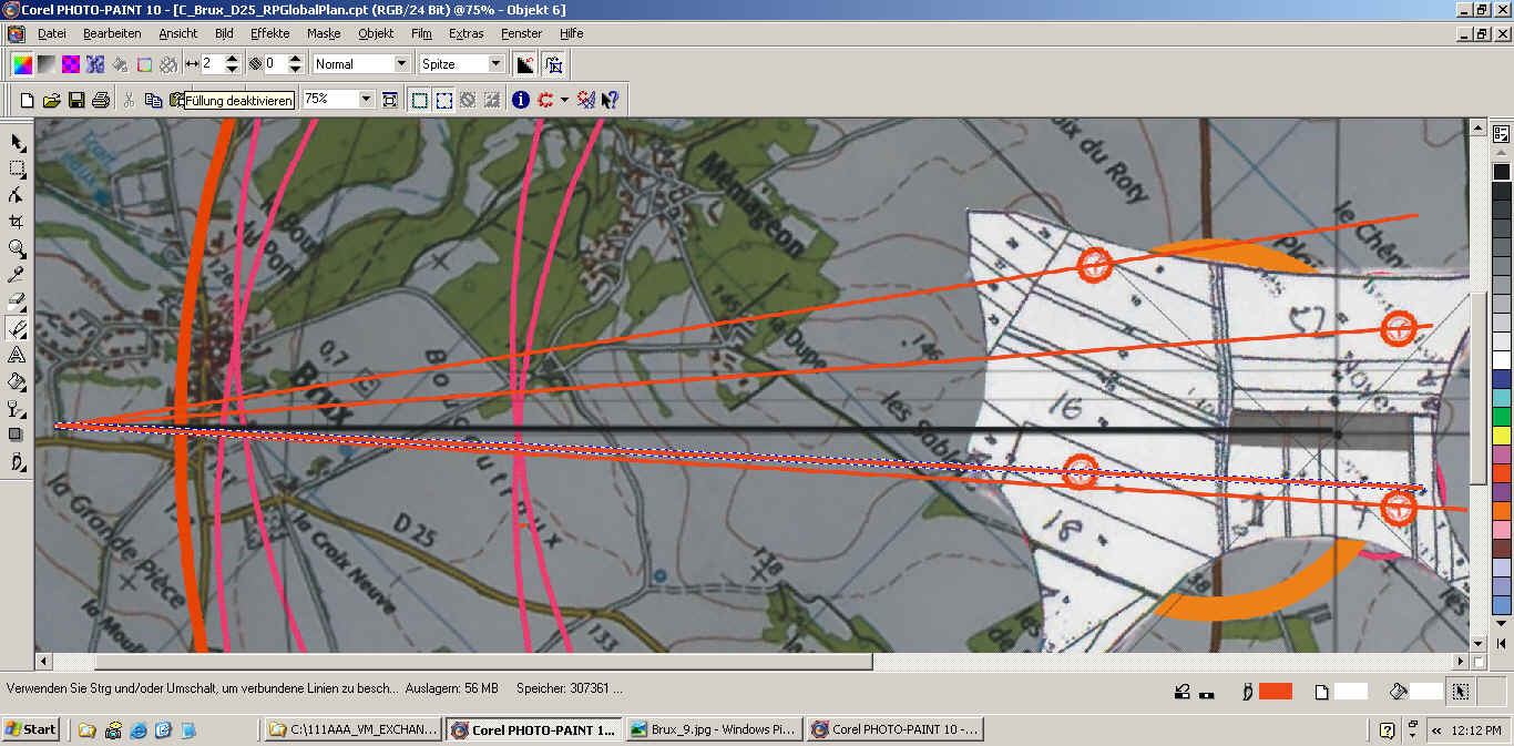 |
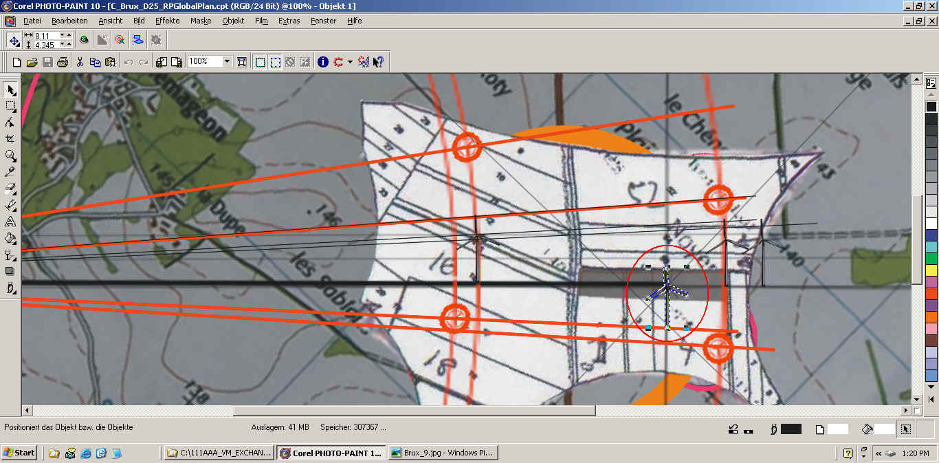
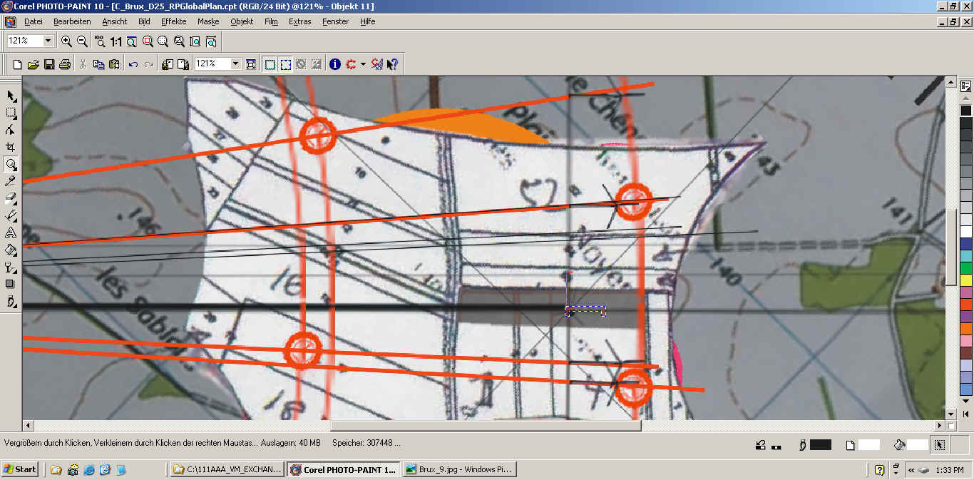
ENGLISH:
Red circles passing through the turbine positions are now drawn around
the camera position in order to register the distance of each turbine
onto the construction plane. The intersection of each circle with
the base of the construction plane indicates the distance of each wind
turbine from the camera. A right angle projection of each of these
points onto the line of the maximal height of the turbines defines the
points which result in the projection lines when connected with the
camera position (blkack lines in the screen shots, but the red line in
the introduction above). |
FRANCAIS:
Des cercles rouges sont tirés autour la caméra pour rapporter la
distance de chaque éolienne sur le plan de construction.
L'intersection de chaque cercle avec la ligne de base du plan de
construction donne la distance de chaque éolienne à la caméra. La
projection à angle droit vers la ligne de la hauteur maximale définira
le point qui permet de construire la ligne de projection sur le plan
de projection (en rouge en haut dans l'introduction et en noir
ci-dessous). |
|
 |
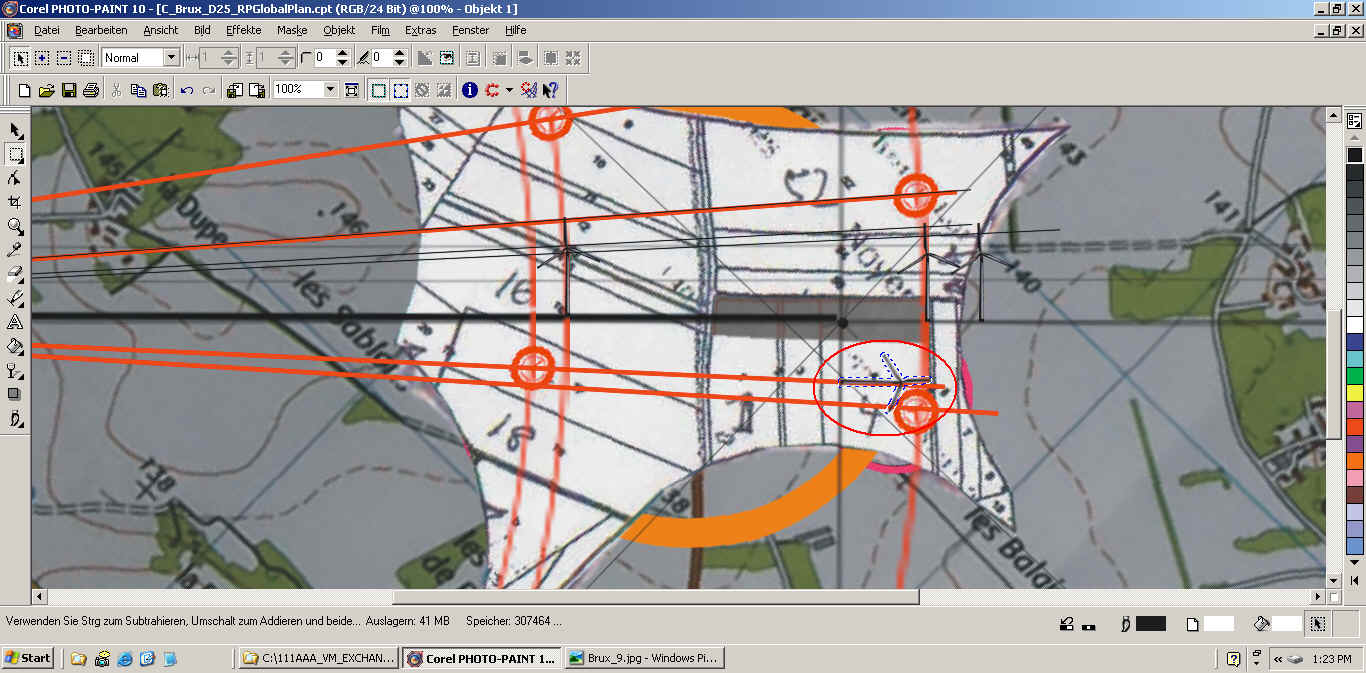
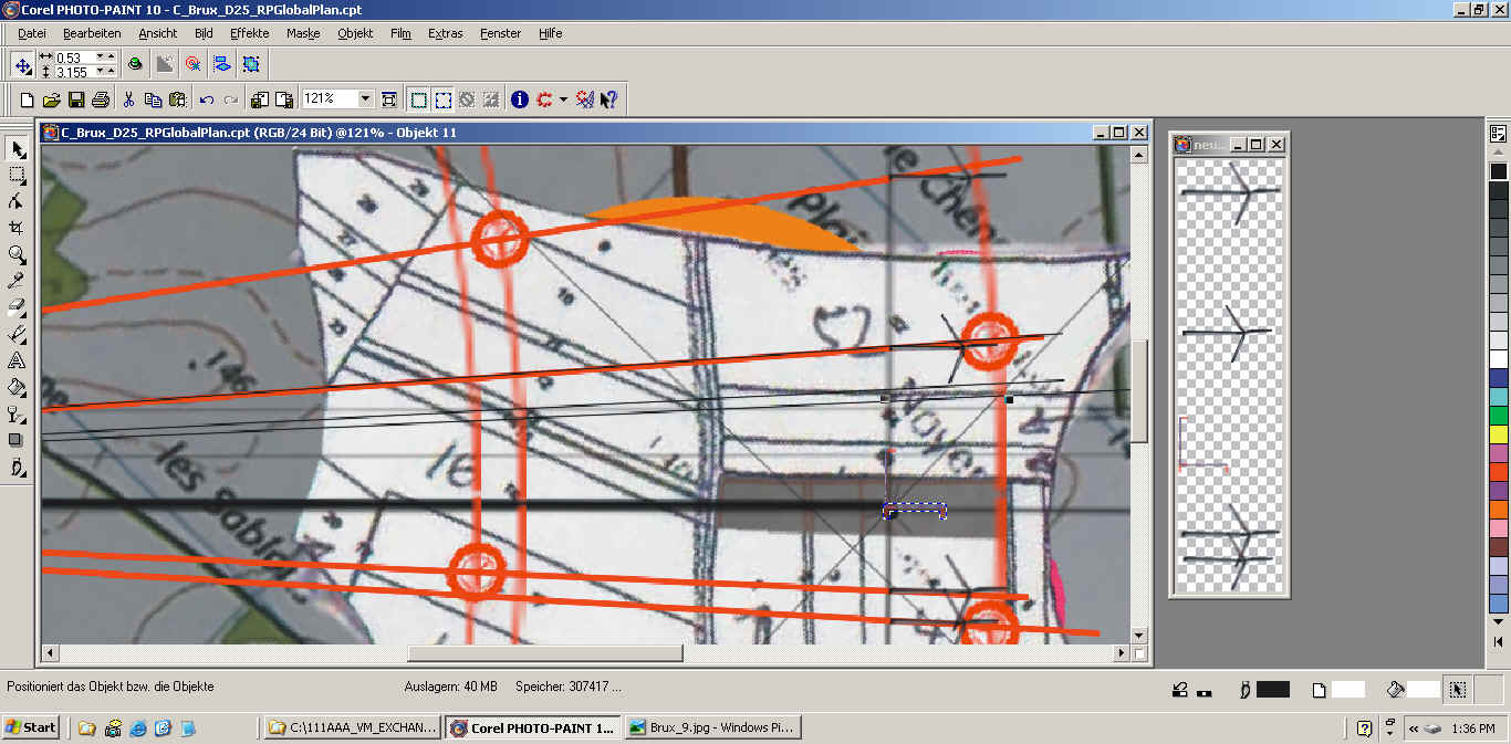
ENGLISH:
The black projection lines have been introduced and they must of course
been drawn to cross the projection plane. |
FRANCAIS:
Les lignes noires de projections des hauteurs des éoliennes vues de la
caméra vers la plaine de projection sont introduites. |
|
 |
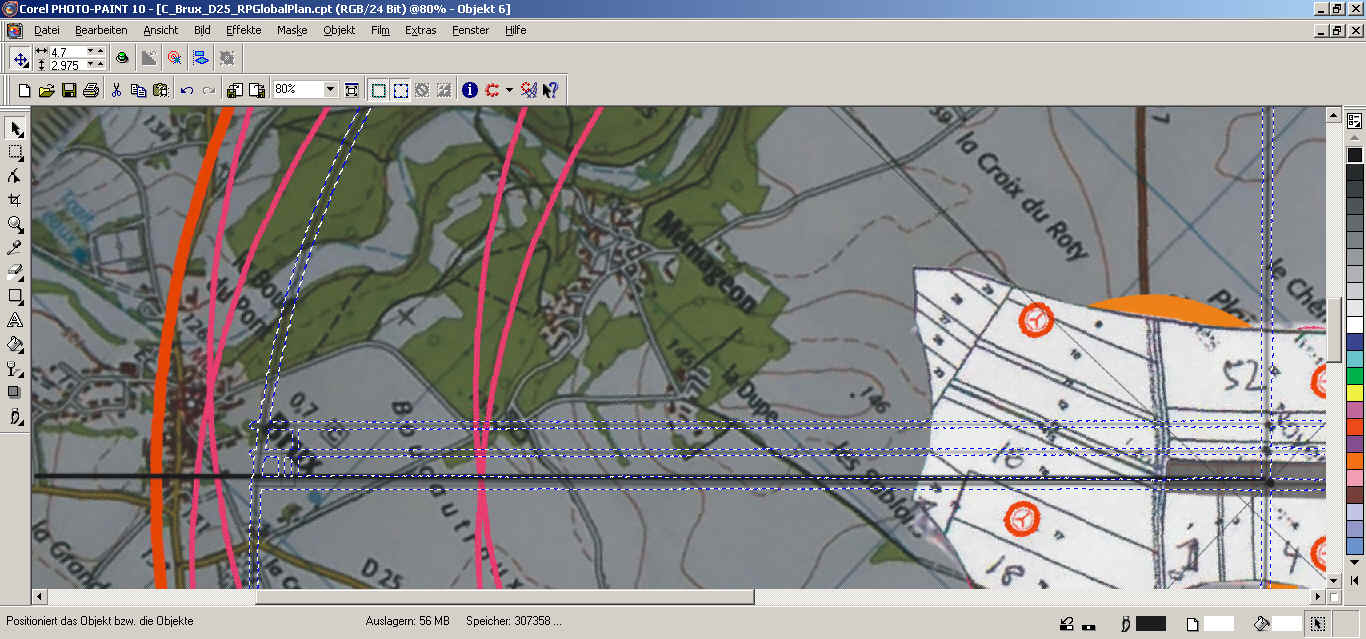
ENGLISH:
The image of the biggest apparent turbine, thus the one closest to the
camera is introduced. She will bring the biggest projection onto the
projection plane. The image of the turbine is scaled by placing its foot
on the cross point of construction and projection planes and the upper
point of the rotor on the intersection point of its line of projection
with the plane of projection (the vertical line which passes the
position of the wind measuring tower).
|
FRANCAIS:
L'image de la plus proche éolienne, donc celle qui donnera la plus
grande projection sur le plan de projection, est introduite et agrandie
à la bonne hauteur, c'est à dire à l'intersection de sa ligne de
projection avec le plan de projection (la verticale qui passe à travers la
position de la tour anémométrique de référence). |
|
 |
ENGLISH:
The plain of projection is shown as a single line as seen from above.
This plane can however also been thought as being flipped away from the
camera. We can thus use this plane to construct the complete image
as seen by the camera. Once the turbine has the correct size (height) it
is thus draged to the correct position on the projection plane. |
FRANCAIS:
Le plan de projection est montré d'en haut comme une ligne mais elle
peut aussi être comprise étant couchée dans ce cas vers la gauche donc
dans le sens de la vue. Une fois l'éolienne à la bonne
taille dans le plan de construction elle est donc poussée au bon endroit
sur le plan de projection. |
|
 |
ENGLISH:
Once the foot is positioned on the intersection of its red line with the
projection plane it can be turned by 90 degrees away from the camera. |
FRANCAIS:
Il ne reste qu'à la tourner par 90 degrés pour la montrer dans le
sens de la vue. |
|
 |
ENGLISH:
The same procedure for the next and all other tcurbines. |
FRANCAIS:
La même chose est faite pour la prochaine éolienne et ainsi de suite. |
|
 |
|
 |
ENGLISH:
It is of primordial importance to now include the height of the
reference tower, of course positioned at the intersection of the
construction and the projection planes and alligned away from the
camera. |
FRANCAIS:
Il est d'importance primordiale d'ajouter la référence de la hauteur de la
tour anémométrique.. |
|
 |
|
|
|
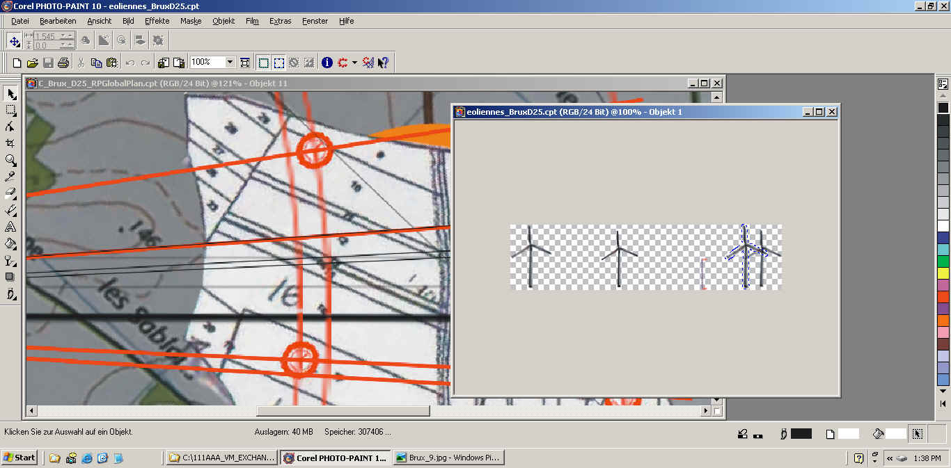
ENGLISH:
All of items collected on the projection plane, all turbines with the
correct relative heights and correct position along with the reference
tower height (all at the same scale) are now copy pasted to a new image
on transparent background. This image can then be turned by -90
degrees and is thus ready to be introduced on the digital picture of the
landscape which of course must also contain the reference tower. |
FRANCAIS:
L'ensemble des ajouts (éoliennes à la bonne hauteur et distribution à la
même échelle avec la référence, la tour anémométrique) est copié et
collé dans une nouvelle image sur fond transparent. Celle ci peut être
tournée par -90 dégrés pour être insérée sur une photo numérique
contenant bien sur, la tour anémométrique de référence. |
|
 |
|
 |
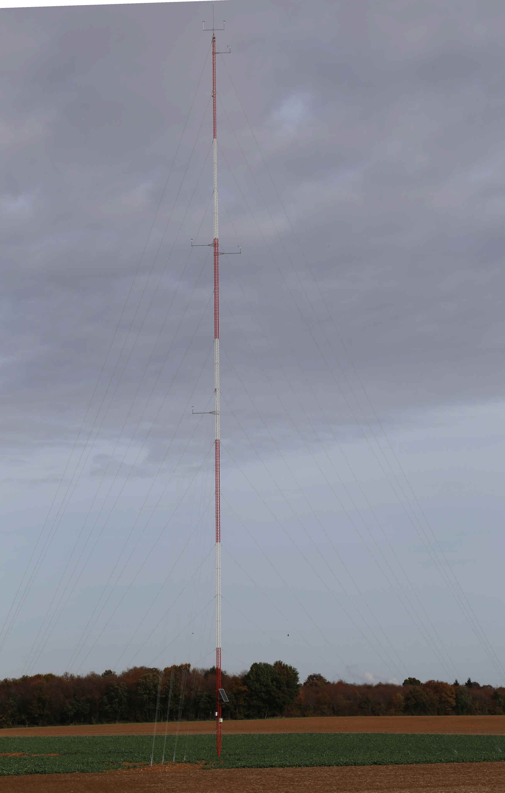
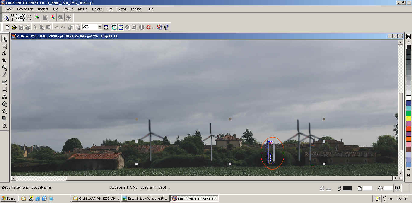
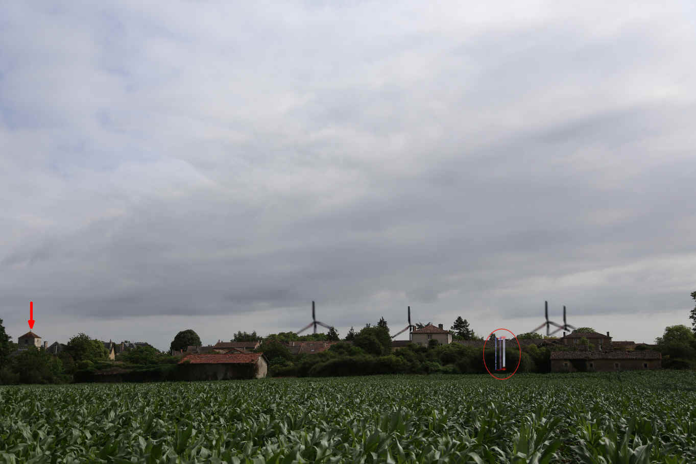
ENGLISH:
It is important that the wind measuring reference tower is well visible
on the enlarged high resolution picture (I use a Canon EOS 6D camera).
At least one full 12 meter sector of the tower must be visible.
This permits to reconstruct the full height of the tower.
For more precision of the comparison with the zoomed view of the tower
an internal reference of the picture has also been used: the
height of a stable which happens to equal the apparent full height of
the reference tower. It
results a impressive visualization of the disastrous impact of the
RP-Global project on the village of Brux with its protected heritage
medieval church (visible at the extreme left side in the last picture of
the sequence). |
FRANCAIS:
Il est important que la tour anémométrique soit bien visible sur au
moins un segment de 12m, ce qui permet de trouver la position du pied
et donc la hauteur de toute la tour sur la photo utilisée. Une
hauteur existante sur la photo, la hauteur d'une grange a été incluse pour plus
de précision pour traduire l'information d'une photo par zoom pour cette
photo de vue large qui démontre la co-visibilité des éoliennes avec la tour de l'église
romane classée monument historique pour le village de Brux (voir à
l'extrême gauche sur la dernière image de la séquence). |
|
 |
|
 |
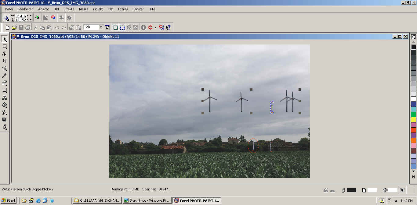
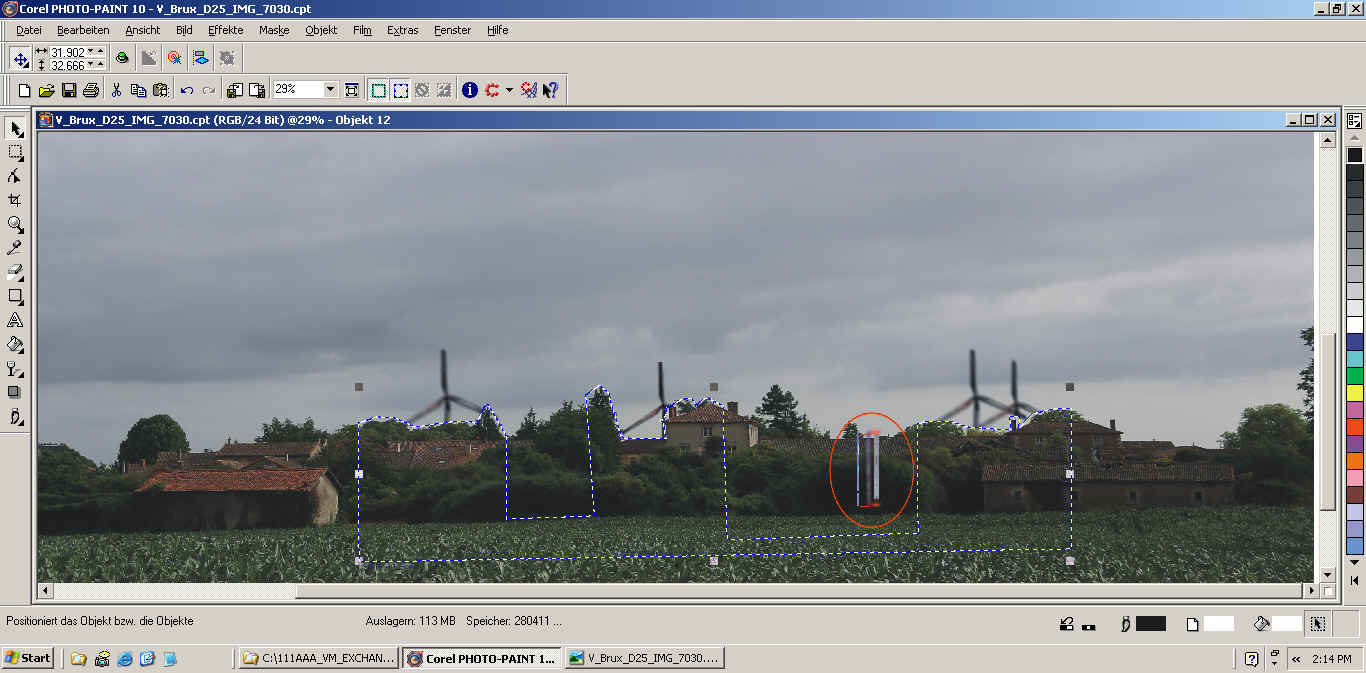
ENGLISH:
After the scaling of the imported projection image using the height of
the reference tower, the added parts are dragged to above the skyline
again in order to be able to hide the non visible parts of the added
image. |
FRANCAIS:
Après l'ajustement de l'image apporté avec la tour de référence visible
sur la photo les ajouts sont repoussés pour copier les fonds pour pouvoir
cacher les parties cachées par le fonds. |
|
 |
|
 |
|
 |
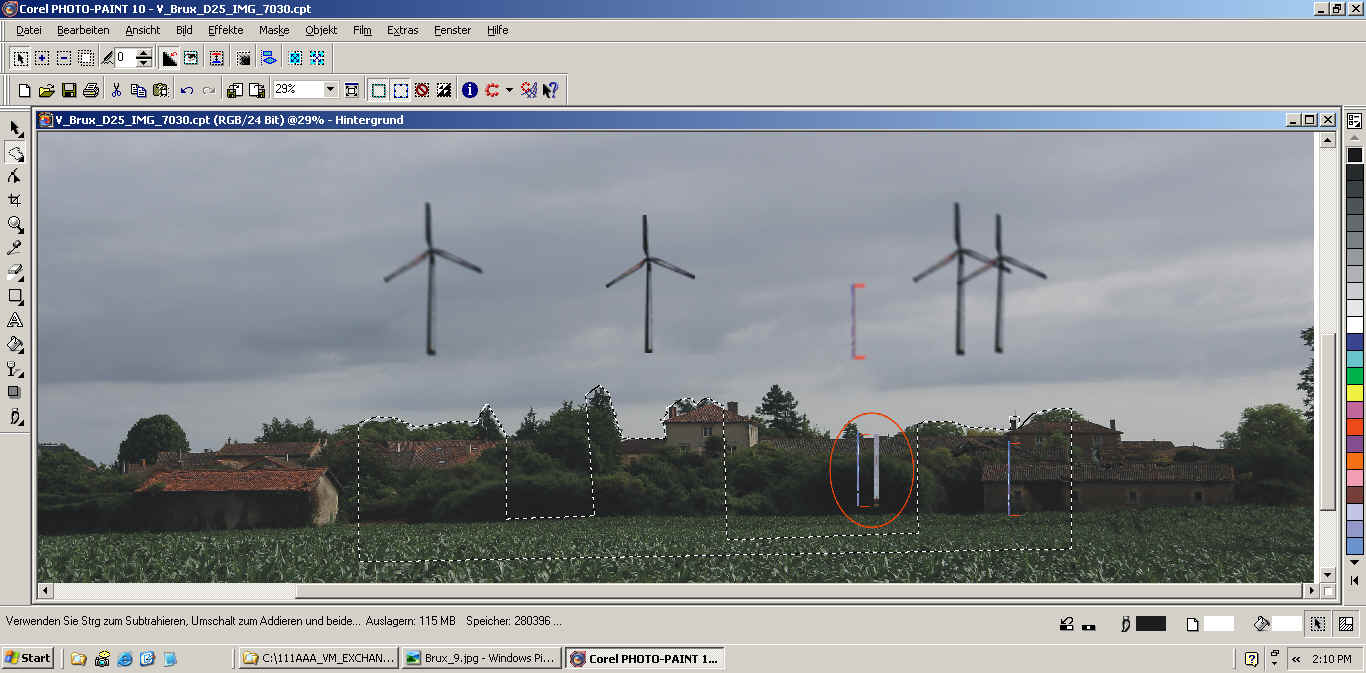
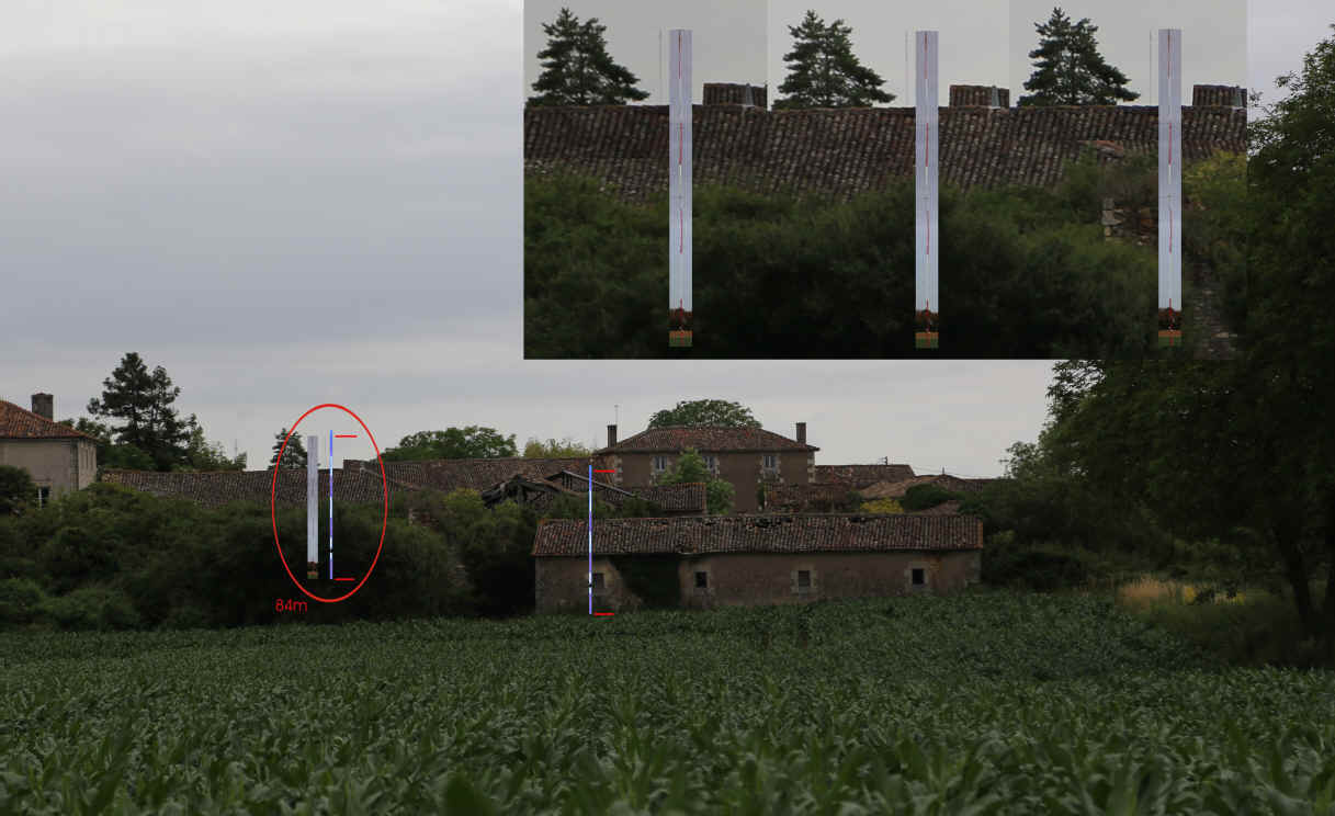
ENGLISH:
For all of the visual impact synthesis presented on windfarmfree.com
three images are always presented: a zoomed view of the wind
measuring tower from exactly the same position as the wide angle picture
used for presenting the analysis, the geometric construction as
described above and finally the visual impact picture showing the
results of the analysis. Note that three distinct pictures have
been used in this case to identify the apparent heights of wind
measuring tower as only one single complete 12 meter sector is visible
in this case. Note also that the distance from the bottom of the
stable to the middle of the middle left corner stone of the house behind
it has been used as an internal reference to transfer the scale
information from the zoomed to the wide angle picture. |
FRANCAIS:
Trois images sont présentées pour toutes les analyses d'impacts visuels du
projet de RP-Global présenté sur windfarmfree.com: une première image
avec zoom prise telle quelle avec la caméra, la construction décrite
ci-dessus et finalement l'analyse visuelle d'une image en grand angle.
Trois photos ont étés analysées pour déterminer la taille apparente de
la tour anémométrique dans l'exemple présenté ici car seul une des
sections de 12 mètres est visible en entier dans ce cas. De plus, la hauteur totale
apparente de la tour a été rapportée sur une référence interne de
l'image: la distance entre le bas de la grange à droite de la tour et le milieu d'une pierre du coin de l'habitation derrière la grange. Cela pour
vérifier la taille apparente de la tour anémométrique de référence sur
l'image en grand angle. |
|