Ce n’est que dans l’époque baroque que l’unité entre maison et jardin déjà recherché dans la renaissance atteint la perfection en alignant l’architecture de préférence sur le paysage et en permettant l’architecture de se continuer dans l’espace libre du jardin....
A perfect harmony between the landscape and man made constructions was in France only achieved in the baroque time. In the context of the flat landscapes of France the ideas of the Italian renaissance were translated by aligning the architecture with the landscape and by modeling the the gardens by creating infinite views by creating baroque axis...
Here you will learn how to construct such synthesis of
the visual impact of wind turbines. It takes a little bit of mathematics, but I
have prepared an EXCEL spread sheet for you so you do not need to understand the
formulas shown. Full transparency is of course important to be able to
defend a court case and for this reasons all calculations are shown here!
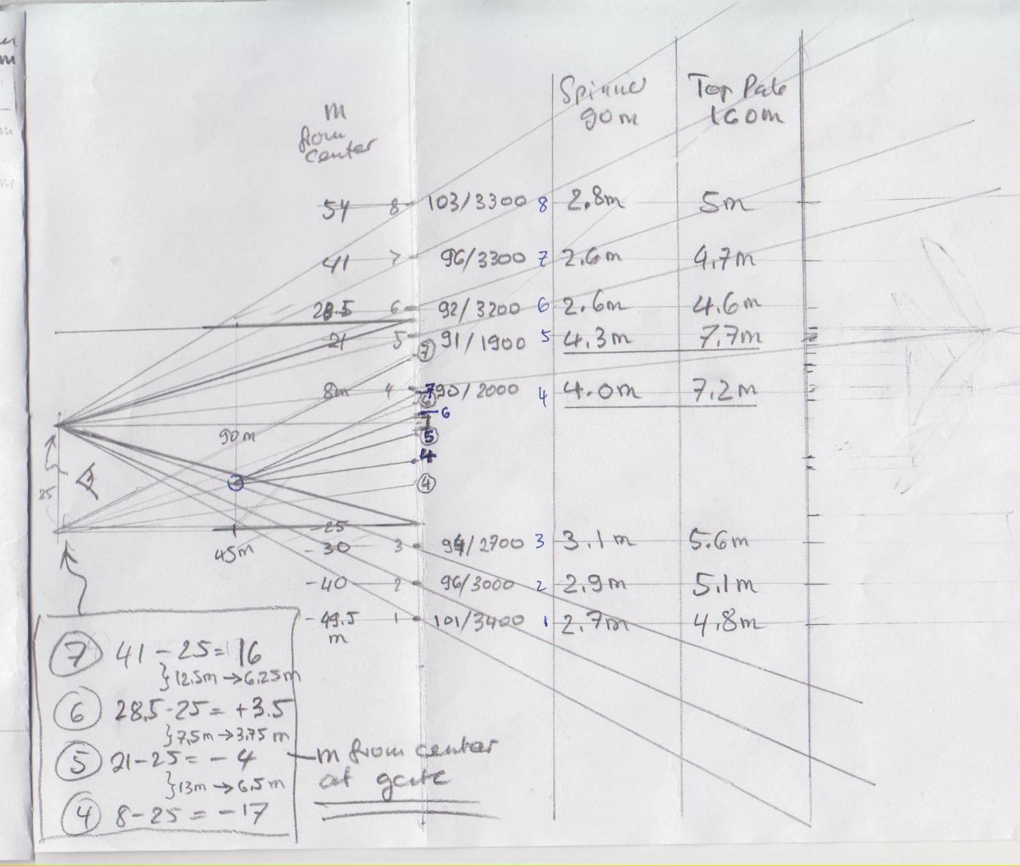
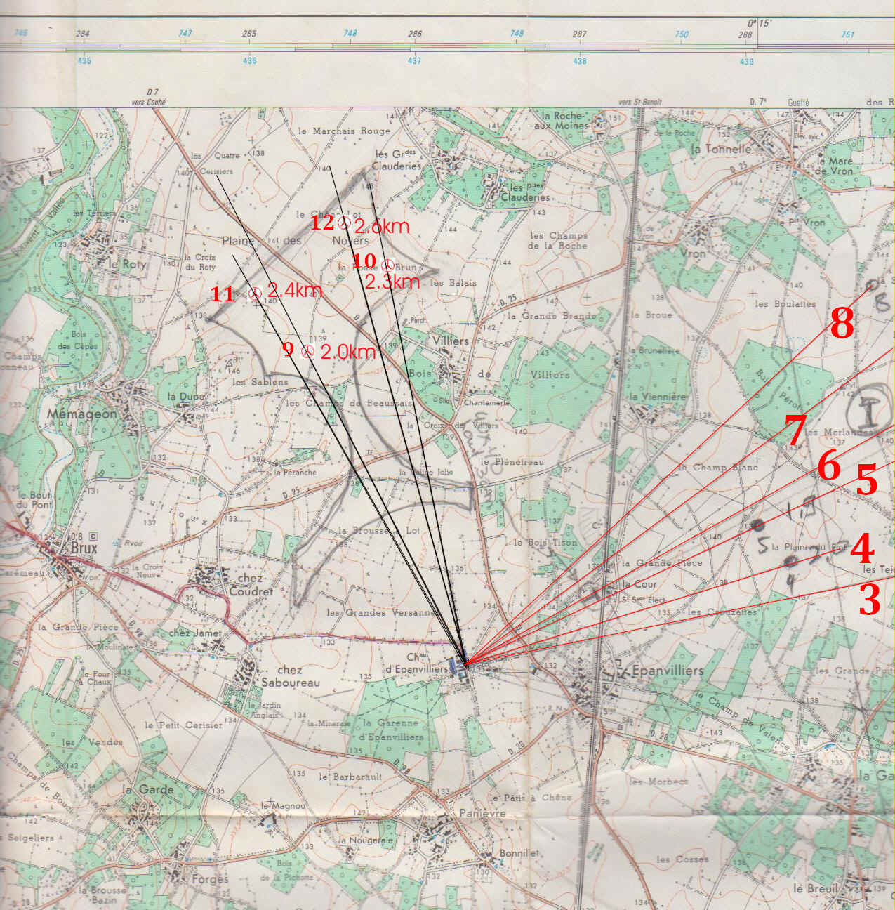
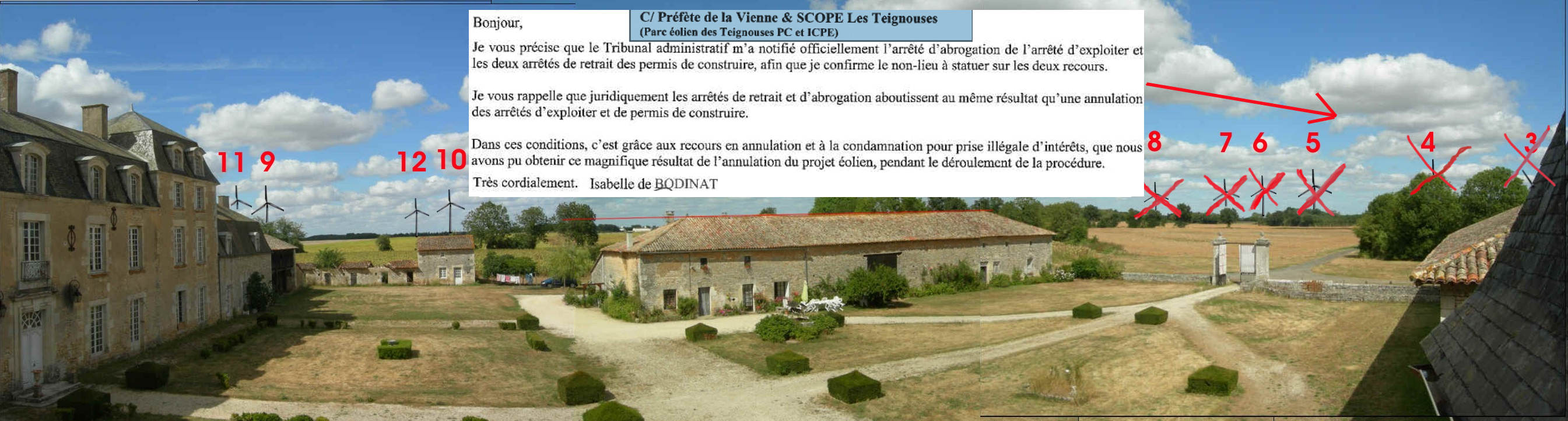
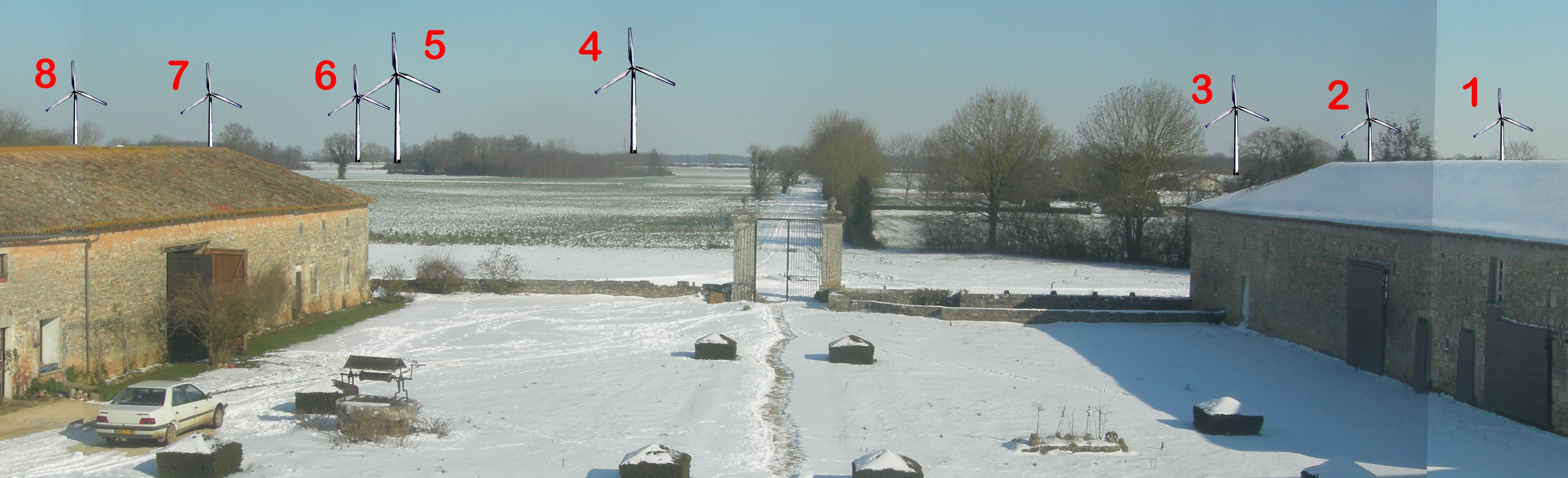
Principle of the construction is a three step procedure: 1) Distance and
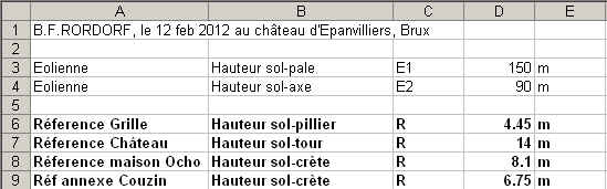
height of the planned turbine installation must be known. 2) Objects of
known height and width must be present on the photographs used for the
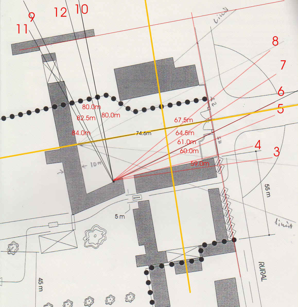
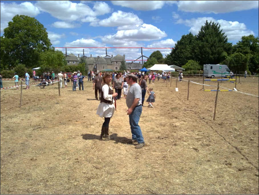
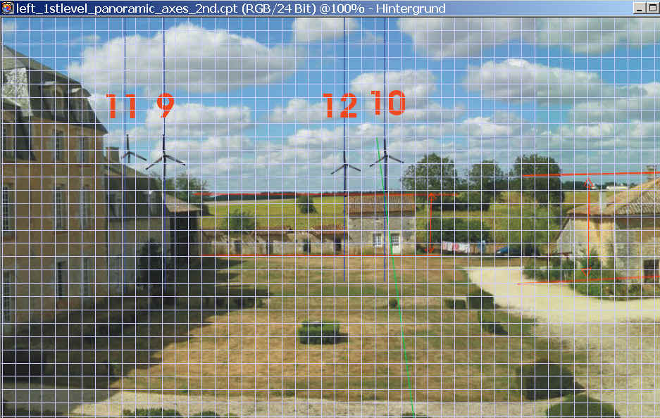
constructions. In the above example the height and the distance of the two
pillars of the gate have been measured. This then permits to calculate the
projection of the turbines in meters onto the plane of these comparators (in the
example, the vertical plane defined by the two pilars of the gate. The
center of the gate also defines the baroque axis shown by the 4 bushes and the
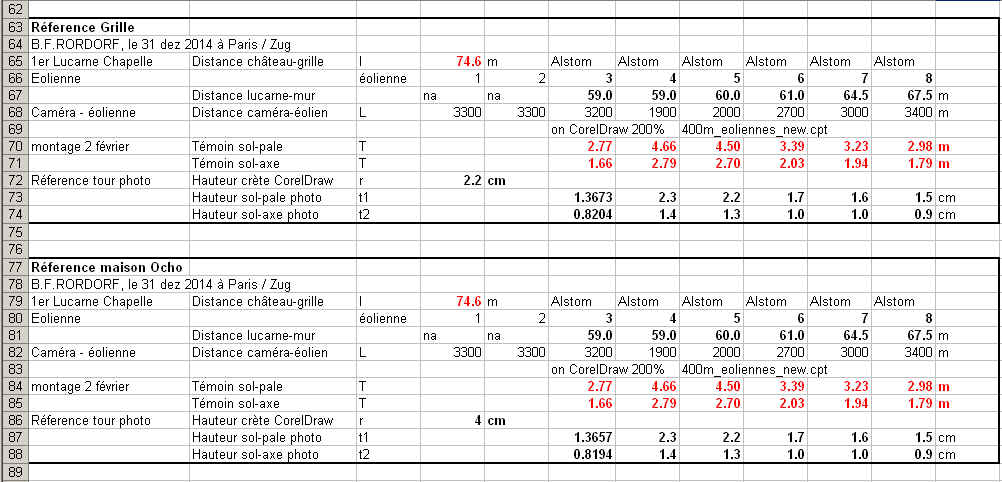
two pillars) 3) The final construction is then made either directly
on a print in millimeters or better in a computer software in pixels
or any internal measure inherent to the software used (such as AUTOCAD, AUTODESK
3D-Studio, or Coreldraw). The results of 2) must thus be re-calculated for step
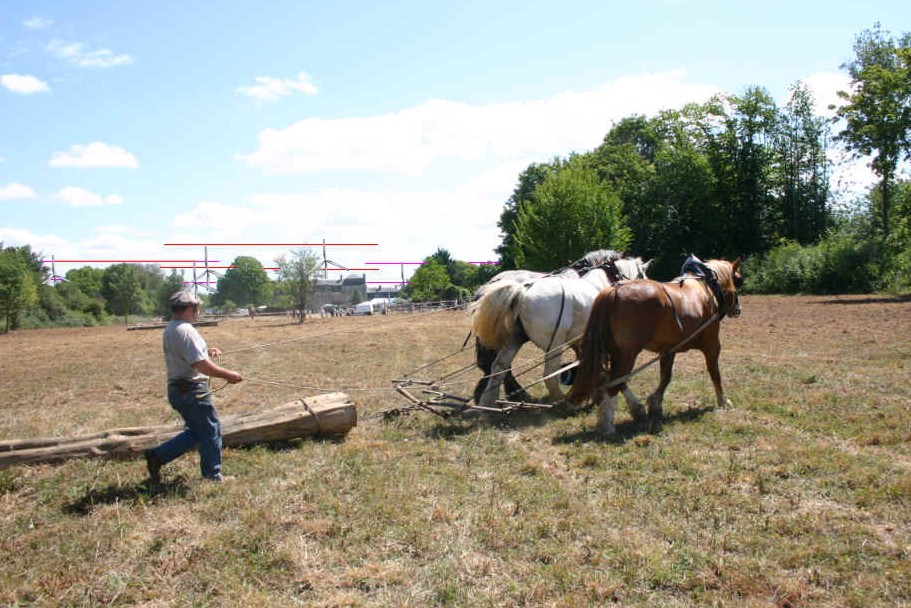
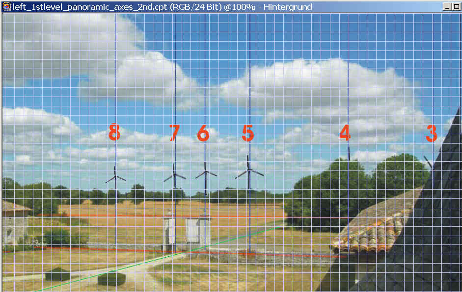
3) in order to be able to scale the picture of a turbine which is then placed on
the correct spot (vertical and horizontal position of the basement of the
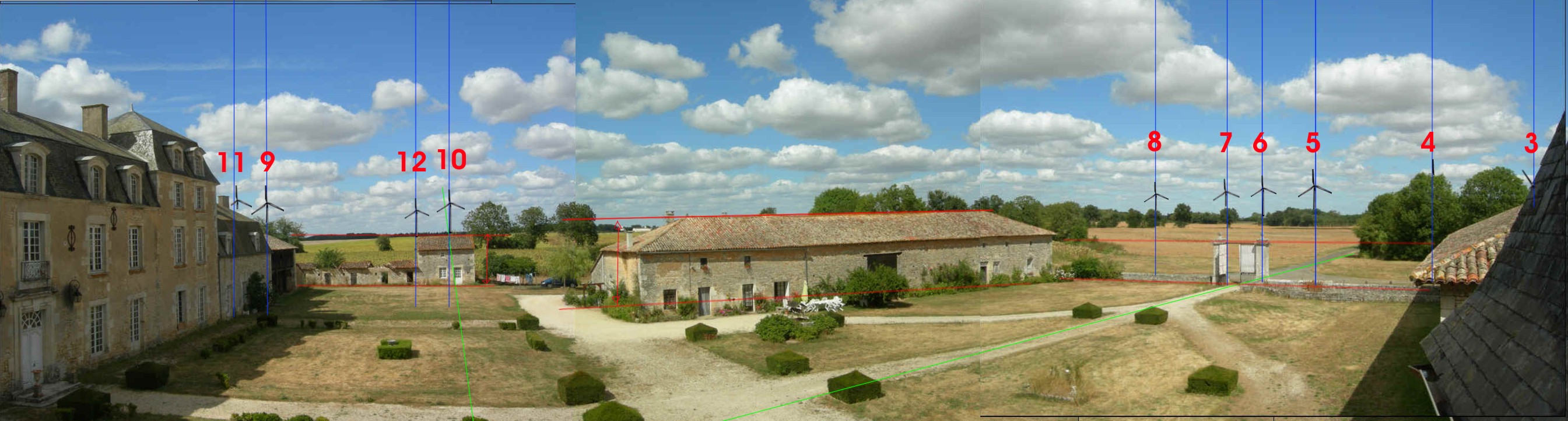
turbine). The lower part of the turbine must be cut if obstructed (as for
turbine 8, 7, 4, 2 and 1 in the above picture).
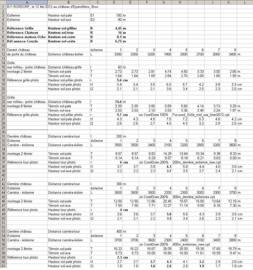
Both the hight from the ground to the axis
of the turbine and the total hight from the ground to the top of the propeller
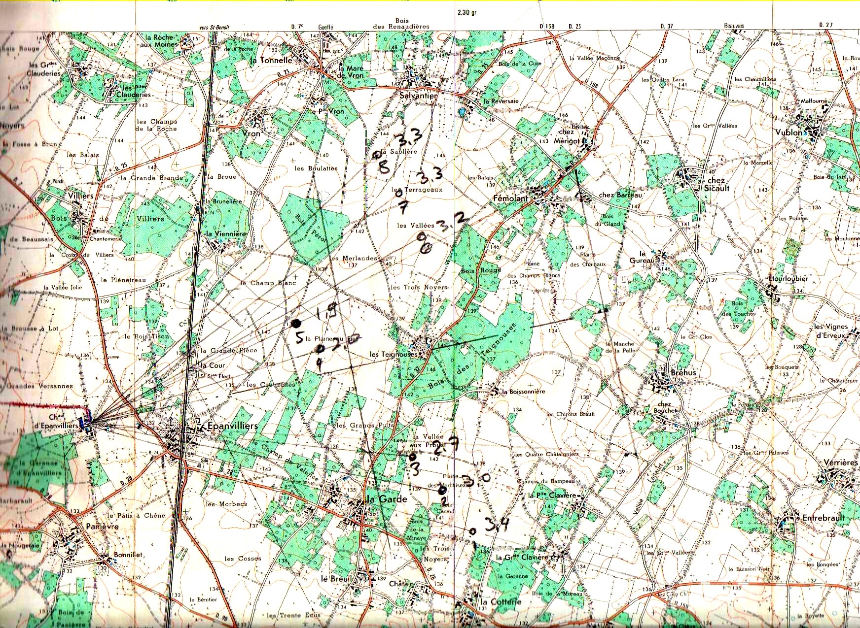
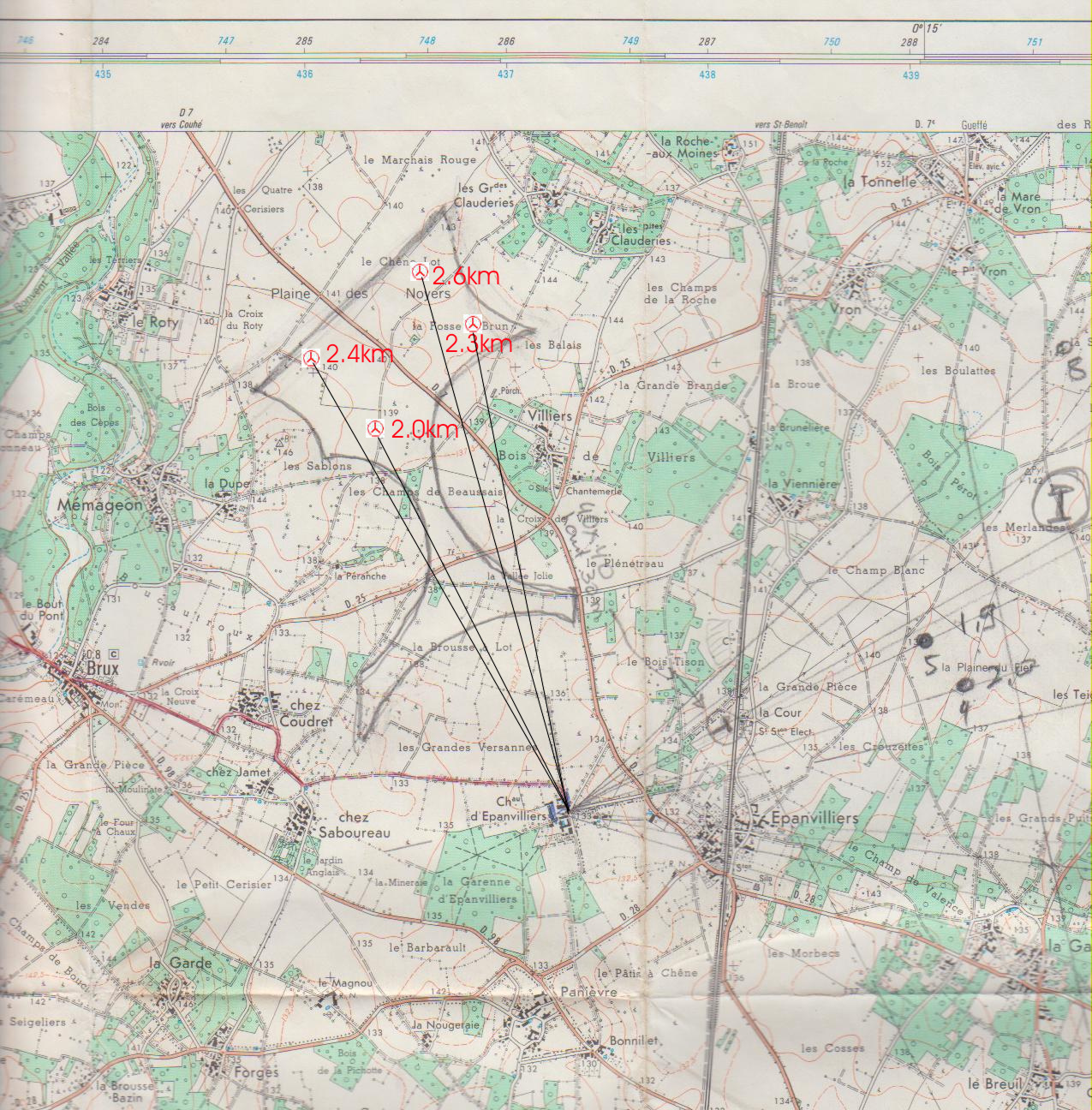
blade in vertical upright position must be known. Secondly you must determine
the distance from the camera (point of observation) to the placement of the
installation in meters by using a map of at least 1:25000 (250m per cm). As
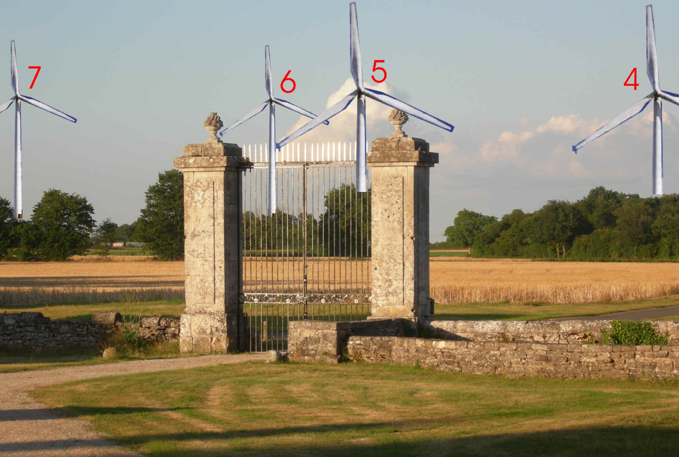
indicated one must also know the dimensions and placement of the comparative
objects. They must of course be present on the photographs used for the
constructions: in the above example the hight of the pillars, the distance of
the two pillars, the mutual distance of the two corners of the buildings shown
(below turbines 6 and 5, and left below turbine 3).
Je
vous montre ici comment construire une telle synthèse de l'impact visuelle
d'installation de générateurs éolien. Un petit peu de mathématique est
inévitable, mais je vous ai préparé un EXCEL qui vous permets de faire de
synthèses sans comprendre tous les formules. Une transparence complète est d'importance
par contre pour pouvoir utiliser vos résultats dans des litiges judiciaires!
Le principe de la construction est une procédure à trois pas: 1) La distance et
la hauteur de la turbine prévu doit être connu. 2) Des objets de référence
de hauteurs et de largeurs connus doivent être présent sur les images
utilisés pour les constructions. Dans l'exemple de ci-dessus la hauteur et
la distance mutuelle des deux piliers de la grille d'entré ont été mesurés. Ceci
permet de calculer la projection des turbines en mètres sur la pleine verticale
des objets de comparaison (dans l'exemple la pleine verticale défini par
les deux piliers de la grille. Le centre de la grille définit en plus une des
deux fameuses axes baroques du château qui passe entre les quatre bosquets de
buis et les deux piliers) 3) La construction finale est faite directement sur un
image imprimé en millimétrés ou bien mieux sur un logiciel d'images sur
ordinateur en pixel ou en tout mesure interne comme défini par le logiciel
(par exemple AUTO CAD, AUTO DESK 3D-Studio, ou Coreldraw). Les résultats de 2)
doivent donc être re-calculé pour le pas 3) pour permettre d'ajuster l'image
d'une turbine à la bonne taille et de la placer ou bon endroit sur l'image (la
position verticale et horizontale du pied de la turbine). Bien entendu il se
peut que la bas de la tige est caché dans l'image utilisé (comme par exemple des
turbines 8, 7, 4, 2 et 1 dans l'image de ci-dessus).
Tous deux la hauteur sol - position de l'axe de la turbine et le total de
la taille du sol à la pointe du rotor en position vertical vers le haut doivent
être connus. Deuxièmement il faut évaluer la distance entre la turbine et la
camera (le point d'observation) en mètres en utilisant une carte d'au moins
1:25000 (250m par cm). Bien entendu il faut aussi connaître les dimensions et
les distances et les tailles des objets de référence, qui doivent évidemment
être présents sur les images utilisés pour les constructions. Dans l'exemple
ci-dessus la hauteur des piliers, la distance entre les piliers et la distance
entre des deux coins des bâtiments (en bas des turbines 6 et 5, et en bas et
gauche de turbine 3).....
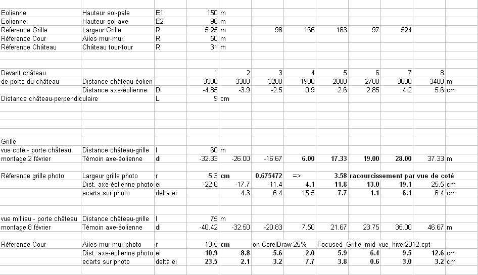
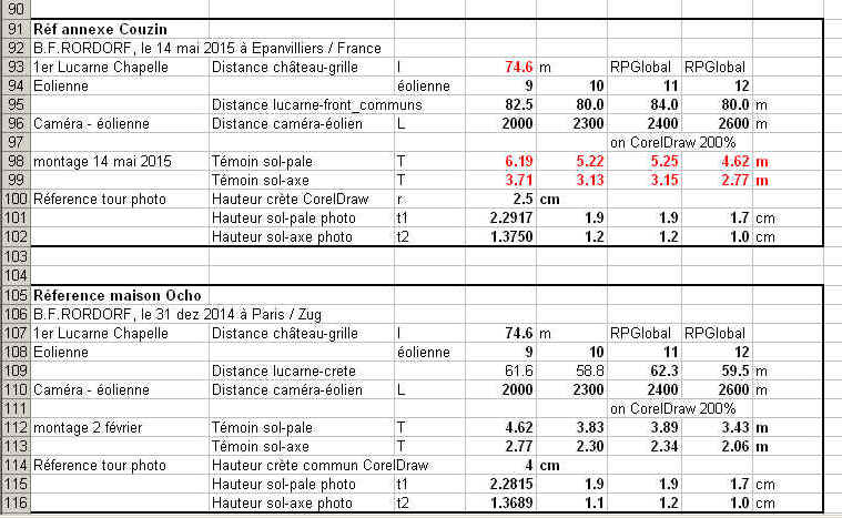
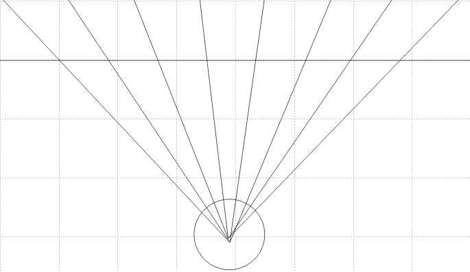
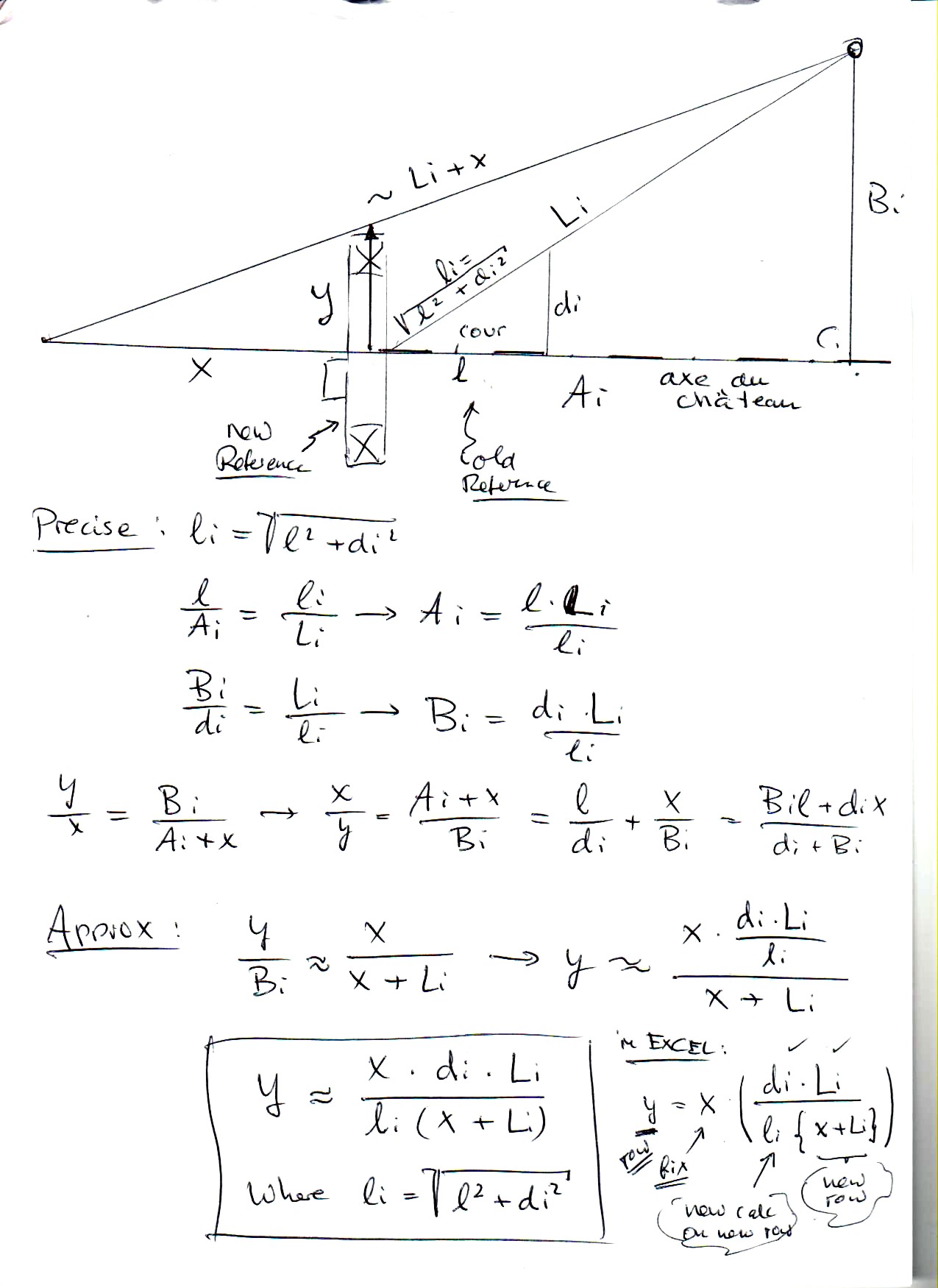
| A) Hight Aa - steps 1 and 2 of above) E = full hight of turbine in meters, T= Calculated hight in meters projection of on vertical reference plane, R hight of reference object (pillar). L distance turbine to camera in meters, and l distance of reference plane to camera in meters. Ab - step 3 of above) R see Aa), T see Aa), r = hightr of reference object in millimeters or pixels, and t = hight of turbine on constructed image in millimeters or pixels B) Distribution. Note, the distances Di from the baroque axis is determined on the map (see below) in meters at a fixed distance of L = 4.5km = 4500 m. This prevents from having to do trigonometric calculations using angles. Ba - steps 1 and 2 of above), l = distance of reference plane to camera in meters, and di = Calculated distance from baroque axis of turbine projection on reference plane in meters. Bb - step 3 of above), R = with of reference object in meters (distance of corners of the two buildings), r = with of reference object on image in millimeters or pixels and ei = calculated distance of turbine from baroque axis in constructed image in millimeters or pixels. |
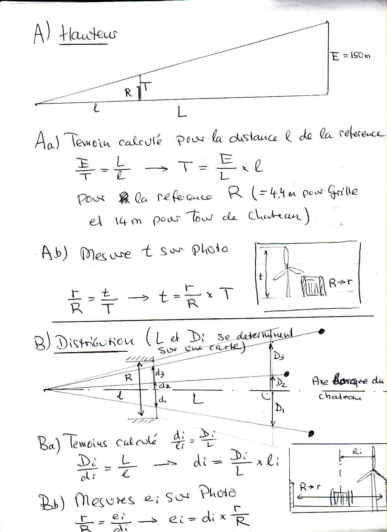 |
A) Hauteur Aa - pas 1 et 2 de ci-dessus) E = hauteur de la turbine in mètres, T= hauteur calculé de la projection sur la pleine de référence plane, R hauteur de l'objet de référence (pilier). La distance entre turbine et camera en mètres, et la distance entre la pleine de référence plane et la camera en mètres. Ab - pas 3 ci-dessus) R voir Aa), T voir Aa), r = hauteur de la référence en millimétrés or pixels, et t = hauteur de la turbine de l' image de synthèse en millimètres ou pixels. B) Distribution. Notez, la distances Di l'axe baroque est évalué sur la carte (voir en bas) en mètres et à distance fixé de L = 4.5km = 4500 m. Cela empêche de devoir faire des calculs trigonométriques en utilisant des angles. Ba - pas 1 et 2 ci-dessus), l = distance entre la pleine de référence et la camera en mètres, et di = distance calculé entre la projection de turbine et l' axe baroque sur la pleine de référence en mètres. Bb - pas 3 ci-dessus), R = largeur de l'objecte de référence en mètres (distance des deux coins des bâtiments), r = largeur de la référence sur l' image en millimètres ou pixels et ei = distance calculé de la turbine de l'axe baroque sur l' image de synthèse en millimètres or pixels. |
 |
 |
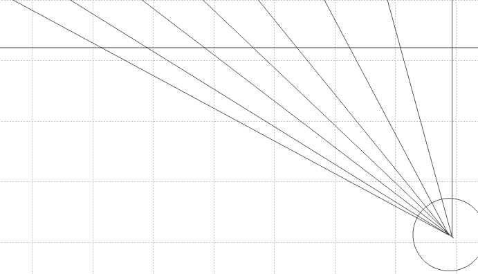 |
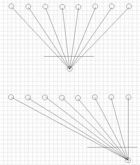
| Correction for off axis camera Strictly speaking the above formulas for the distribution of the projections onto the reference plane are only correct if the camera is located on the baroque axis and a correction must be included for an off-axis projection (skewed projection onto the reference plane). The formulas are given here without going into details of the calculations. |
 |
Correction pour
camera hors l'axe Les formulas concernant la distribution des projections sur la pleine de référence ci-dessus sont seulement précis pour une camera placé sur l'axe baroque et une correction est nécessaire pour les projections hors l'axe. Les formulas sont développé ici sans donner des explications. |